No CT: 😀😀
That's so typical to life... 🙂
Changes: the guys recommended to use the PE and in this new case you dont
have a fixed common GND point but several local PS GNDs between the caps.
But you still can use this layout as a center tapped one if you would like to...
That's so typical to life... 🙂
Changes: the guys recommended to use the PE and in this new case you dont
have a fixed common GND point but several local PS GNDs between the caps.
But you still can use this layout as a center tapped one if you would like to...
The CT conversion will save money and save space.
There will be no advantage to using 6channels all connected to the same Main Audio Ground (MAG) via 24 rectifiers compared to all six channels connected to the same MAG via 12 rectifiers.
There will be no advantage to using 6channels all connected to the same Main Audio Ground (MAG) via 24 rectifiers compared to all six channels connected to the same MAG via 12 rectifiers.
Hi Andrew,
Where have you got the 24 from? Unless you're including another 12 from the control toroid rectified in the same way?
If this is correct you are suggesting I should create a centre tap right at the toroid output for BOTH (separately of course) and use 6 rectifiers for each?
Thanks
Where have you got the 24 from? Unless you're including another 12 from the control toroid rectified in the same way?
If this is correct you are suggesting I should create a centre tap right at the toroid output for BOTH (separately of course) and use 6 rectifiers for each?
Thanks
Last edited:
A CT connected transformer uses one bridge rectifier to create a dual polarity supply to feed the load.
A dual secondary transformer uses two bridge rectifiers to create two single polarity supplies that get series connected to create the dual polarity supply.
So 4 rectifier diodes becomes 8 rectifier diodes when you use a dual secondary.
So for your 6 PSUs you need 24 recifier diodes for 6 dual supplies from the CT, or you need 48 rectifier diodes for 6 dual supplies from a dual secondary.
Sorry I got my 12 & 24 halved. It should have said 24 & 48, which I typed and changed !
Hi Andrew,
I understand the differences but which one are you suggesting to use?
My 24 and 12 were referring to bridges, so x4 already - so potentially up to 96 diodes if "power toroid" and "control toroid" are to each have dual secondaries for each channel (2 x 6 x 8)
Thanks
I understand the differences but which one are you suggesting to use?
My 24 and 12 were referring to bridges, so x4 already - so potentially up to 96 diodes if "power toroid" and "control toroid" are to each have dual secondaries for each channel (2 x 6 x 8)
Thanks
Last edited:
........... which one are you suggesting to use?
...............
The CT conversion will save money and save space.
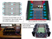
This is still easier than trying to place a common plate across 12 capacitors that cannot all be lined up in "twos". All amps will be identical.
If necessary, a designer could construct one Common Ground Plate over all 12-capacitors, with 6-holes drilled for the center 6-positive screws,
OR
use a PCB with heavy copper layers for greater capacitor placement flexibility, plus reduce some wires by using solder-down relays and diode bridges. The +/- 15V protection power supply could also be built on this PCB.
Attachments
Matt have you already purchased the thyristors as well?
Because I would also suggest one big PS insread of 6 smaller.
And regarding power consumption there are better solutions I guess.
For example I would adjust the bias to zero at the output stage.
Isnt that enough?
Because I would also suggest one big PS insread of 6 smaller.
And regarding power consumption there are better solutions I guess.
For example I would adjust the bias to zero at the output stage.
Isnt that enough?
If necessary, a designer could construct one Common Ground Plate over all 12-capacitors, with 6-holes drilled for the center 6-positive screws,
OR
use a PCB with heavy copper layers for greater capacitor placement flexibility, plus reduce some wires by using solder-down relays and diode bridges. The +/- 15V protection power supply could also be built on this PCB.
Commoning all the capacitors doesn't gain anything since they are already connected together at the 0V terminal at the transformer centre tap?
Creating a PCB with heavy copper layers isn't the easiest option for DIY. I also like the idea for keeping things seperate for modularity in terms of future maintainance / upgrade.
Matt have you already purchased the thyristors as well?
Because I would also suggest one big PS insread of 6 smaller.
And regarding power consumption there are better solutions I guess.
For example I would adjust the bias to zero at the output stage.
Isnt that enough?
If implimented properly I agree this would be a more elegant solution. In keeping with my previous comment I like the idea of it being "plug and play". I.e I don't want extra functionality like a timeout and/or bias interface circuit and control header to set bias current to 0 on the AMP pcb. I want it to be simple and upgradable around the existing control circuitry. I also prefer cutting the power altogether via thyristors since it costs nothing in compromise to do this and OFF really means OFF.
I like the suggestions though 🙂
Matt
Yeah, yeah, we are just brainstorming... 🙂
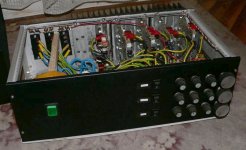
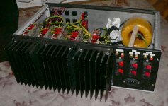
And - if the "P'n'P" approach was already mentioned - what about an
integrated layout when you build each channel with its PS on one PCB?
Then you can spare a lot of air-wiring and you only have to lead the AC lines to
these modules. And you could place each channel as a card on a motherboard.
So 3 channels / side. Similar to the attachment. (I made this ugly one about 15 years ago... )
)
I started with 2 or 3 bigger trafo then I kept only one ~200VA, and it was more than enough for HT... 😛
And - if the "P'n'P" approach was already mentioned - what about an
integrated layout when you build each channel with its PS on one PCB?
Then you can spare a lot of air-wiring and you only have to lead the AC lines to
these modules. And you could place each channel as a card on a motherboard.
So 3 channels / side. Similar to the attachment. (I made this ugly one about 15 years ago...
)I started with 2 or 3 bigger trafo then I kept only one ~200VA, and it was more than enough for HT... 😛
Attachments
matt09,
Heavy metal.....I just pulled on one of my Krell KSA250 amps as a reminder.... set-and-forget is desirable. 🙂
Do you have a collection of amplifier schematics which you are considering? Using a proven design where PCBs are still available seems desirable, especially with the increasing shortage of the "really nifty" transistors.
Have you simulated your heatsinks for 600-700 total watts of Class A/B power?
Six identical 100W amps?
Two 200W sub amps + four 100W amps?
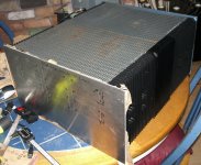
Heavy indeed.. the bare case with heatsinks is coming in at 23kg, another 22kg for the transformer and that's 45 before anything else! Total weight is looking to be around 56kg. I really don't want to use casters as they're look ugly although I'm now having to reconsider.
Regarding the amp schematics this is something I was going to ask about soon. There are SO many different amps on here I have no idea which to use. I will certainly be going with a proven design with available gerbers and/or boards though, I can etch them myself if necessary. All amps will be identical and bridgable in pairs.
I want to use a schematic representative of minimal compromise on performance, across the range of relevant metrics - this is an all out best I can possibly make project since budget isn't a limiting factor.
I haven't simulated the heatsinks but I know from the size and weight they will be good for 700W+ Each amp will be Class AB biased a few watts into Class A.
My AC primarys are 55-0-55 so I should be hitting 250W-ish which I want to double into 4ohm.
The heatsinks aren't quite large enough to support every single channel driven to clipping with 4ohm load - even with programme material, but in this case thermal cuts will take over. This scenario is extremely unlikely anyway as I really have no reason to be pushing 3kW!.
The power saving design also allows each channel to be high output since any unused channel will have the AC line to the caps cut anyway so 0 standing dissipation. In total I estimate I will need 8 output devices per amp minimum (4 per side), 48 devices total.
Last edited:

Here is a latest "systems" drawing of the whole amp, maybe I should start a separate build thread.
Hi,
Can you attach a bigger image or pdf?
I am using my small monitor and I can read all of it very easily.
Dimensions: 3,226px × 1,248px
Dimensions: 3,226px × 1,248px
Yes, remember to enlarge!
It's not the greatest diagram I know, It's been added to over the course of a year.
It began life in a software program I lost / didn't reinstall so I've been editing it in paint since.
I made an under estimation, looks like to double my power into 4 ohm I'll need minimum of 6 per side, per amp = 72. Damn..
Last edited:
Max Pout ~ total Pmax cold / 5 when using BJT (divide by 6 if using 1943/5200, or running the heatsink very hot).
If you are using 4pair of 180W devices, then Pmax ~ 8*180/5 = 288W
If you are using 4pair of 180W devices, then Pmax ~ 8*180/5 = 288W
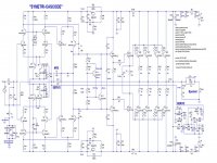
For your schematic collection:
Slewmaster - CFA vs. VFA "Rumble" thread has PCBs for a "SYMETRI" amplifier topology similar to attached "SYMETRI-CASCODE" LTSPICE schematic. A careful thread read is necessary to find the latest schematic and PCB. A cascode front-end allows the use of low noise input transistors. The symetrical 2nd stage assures robust clipping. I have built amps with 10x lower THD, but none which could safely scale up to 75V.
FOR YOUR 75V POWER SUPPLY, you will need to check and re-check the max-voltage specs for all devices and run enough simulations to feel safe. For a 75V power supply I suspect you will find more PA-style medium sound quality Class-B designs than high sound quality Class-A/B.
75V ... Be Afraid....Be Very Afraid!
=========
I can share some simulations if you decide to use opamp based analog protection circuits instead of the PIC microprocessor designs that are now popular.
Attachments
Andrew, thanks for that handy formula.
Can anyone comment if I have enough capacitance per amp? I based my the figure on Classe amps but have since realised this is a bit lower than quite a few designs on here. For ~480W I have 22000 + 4700uF locally, PER side, PER amp.
Linesource, thank you for the contribution, the power supply is indeed a bit troublesome but it was a case of what I could get hold of and I knew it was roughly the correct voltage. I certainly don't want to have to compromise on the sound quality because of it. I am also looking at the Ovation 250 and the other amps by Andrew Russel.
The simulations may certainly be useful, at the moment I was looking at using this circuit by Alan (who is now banned?) to drive the thyristor gates via isolation.
http://www.diyaudio.com/forums/solid-state/191449-output-relays-62.html
His circuit features built in start up delay with simple three stage low side drive which is all I want.
- Status
- Not open for further replies.
- Home
- Amplifiers
- Solid State
- 6-channel-amplifier-grounding