All my tube equipment uses either GE or RCA 5U4GT tubes, or 5AS4A.
I don't like to play with fire.
I don't know which variant New Sensor reverse engineered, when working out the EH 5U4GB, but they did a quite decent job. That variant is quite unlike other 5U4 "equivalents" made in Russian or Chinese plants. Those other variants are garbage.
BTW, if you come across an Australian AWV made ST bottle 5AS4, don't be afraid to buy.
I've recently tested a large batch of 5U4G/5AS4 for leakage using a common digital insulation resistance meter (megohmmeter). They were all vintage, and the majority were likely pulled from working equipment. I tested at the common 1kVDC level available from that generic type of IR tester, and then at 1500VDC. Of the 33 original, 14 showed no leakage at 1500V for both diode sides. The IR tester can detect very low leakage currents, and even those diodes showing some leakage would still likely be quite fine in use, as the measured leakage current is only at the PIV and reduces as test voltage reduces. The lowest IR was down around 30Meg at 1500V, so peak leakage observed was circa 50uA.
I got the feeling that the vintage used diodes that were showing leakage was mainly due to tungstan metal vapour deposited on to internal surfaces like mica insulators, as quite often the IR level was different per diode side. If that was the case then those valves could still have a long service life if a few ss diodes were added in series.
These tests were with a normally operating heater. A different type of test would be needed to capture what was happening during turn-on for a valve experiencing visible gas discharge.
I also tested each diode for on-voltage characteristic, to see how much difference can be expected - but that is anther topic in itself.
If the fast heater turn-on of a 5U4 is a concern, then a relatively simple fix is to add a NTC thermistor in series, and a relay across the heater voltage to short out the thermistor. I'm just characterising the delay that that provides now, but it seems to be an eminently simple and failsafe method to make the 5U4 act like a 5V4 or even better wrt power supply sequencing.
Last edited:
I don't know which variant New Sensor reverse engineered, when working out the EH 5U4GB, but they did a quite decent job. That variant is quite unlike other 5U4 "equivalents" made in Russian or Chinese plants. Those other variants are garbage.
BTW, if you come across an Australian AWV made ST bottle 5AS4, don't be afraid to buy.
The RCA 5AS4A that's in my 1963 RCA Victor console stereo is the Original tube - dated 1962 - and still performs like new.
Also, I've got a small hoarde (8 or 10) of GE and RCA 5U4GT's tucked away, so I'll never need to buy any....LOL!
If you wire the standby switch after the tank capacitor, it will no longer strain the 5U4.
I assume you are familiar with valve amplifier design and safety.
I assume you are familiar with valve amplifier design and safety.
Cary is notorious for using too much capacitance on their power supplies which is why their xfrmrs are so large. They measure well but will pound those rectifiers. The SLI80 uses a 1200uf after the rectifiers. Couple things you could do.
1-Use better tubes
2-install a softstart on the second switch
3- Replace input cap with smaller cap and configure for CLC if you can fit an inductor under chassis. CLCLC even better if you can fit two
1-Use better tubes
2-install a softstart on the second switch
3- Replace input cap with smaller cap and configure for CLC if you can fit an inductor under chassis. CLCLC even better if you can fit two
Last edited:
First action is : Avoid using the standby switch, lock it in "on". That way the
rectifiers and all other tubes will get a softstart.
Hello,
I am going to use a 5R4GYB with a rather high AC voltage but with a very modest current as well as a choke input.
I checked an offical datasheet published by a French magazine for a 211 amp some decades ago.
There is a graphic to clearify the use of this tube concerning current and AC voltage apllied. The graphic clearly shows two areas. One area where filament and plate voltages may be applied simultaneously and the other area where the filament temperature should be allowed to reach operating temperature ( 10 seconds) before plate voltage is applied.
If hot-switching is required during operation choke-input circuits are recommended. Such circuits limt the hot-switching current to a value no higher than that of the peak plate current.
THIS is information from an offical datasheet so i think it is better to stick to that.
Greetings, Eduard
I don't know which variant New Sensor reverse engineered, when working out the EH 5U4GB, but they did a quite decent job. That variant is quite unlike other 5U4 "equivalents" made in Russian or Chinese plants. Those other variants are garbage.
BTW, if you come across an Australian AWV made ST bottle 5AS4, don't be afraid to buy.
I find it hard to believe that a Winged C 5C3S is "garbage"... Then again vacuum rectification is garbage compared to SS. Is that what you mean?
First action is : Avoid using the standby switch, lock it in "on". That way the
rectifiers and all other tubes will get a softstart.
Hello,
I am going to use a 5R4GYB with a rather high AC voltage but with a very modest current as well as a choke input.
I checked an offical datasheet published by a French magazine for a 211 amp some decades ago.
There is a graphic to clearify the use of this tube concerning current and AC voltage apllied. The graphic clearly shows two areas. One area where filament and plate voltages may be applied simultaneously and the other area where the filament temperature should be allowed to reach operating temperature ( 10 seconds) before plate voltage is applied.
If hot-switching is required during operation choke-input circuits are recommended. Such circuits limt the hot-switching current to a value no higher than that of the peak plate current.
THIS is information from an offical datasheet so i think it is better to stick to that.
Greetings, Eduard
All the fuss and chattering about "soft start" circuits, and "standby switches" has for years now gone on religiously across the internet with the intending fears of tube/equipment failures/protections....
Basically, promoting fear itself.
In reality, which is where I myself intend to live, and stay, I find a lot of this is due to the fact that some modern equipment is just poorly designed in the first place.
And that's a sad state of affairs that I stay away from, knowing what I do about electronic design.
I simply won't allow such things to "nut my brain" and make me paranoid.
If you look at previous amplifier designs rooted in the era/golden age of tubes, you'll never see any of this fussing around with switching/delaying of the high voltage circuits, save for guitar amplifiers and jukeboxes, which were designed to employ a system of "quick-starting" for their particular use.
In home equipment, which, assuming, this and all the other threads/blogs are discussing, there's no real need for "standby" duty, if the equipment was designed properly in the first place.
My 1963 RCA Victor console never needed "standby" crap.
Thousands of "tube era" other consoles and hifi amps didn't need it either.
Fisher, Scott, Harman Kardon, etc etc, never employed delay circuits.
And the tubes lasted for decades, happily.
In another thread here, the discussion about rectifiers (5U4GB, etc) I mentioned the original 5AS4A in my own console, with a date code of 1962, which still performs/tests fine, and that tube drives a chain of 17 other tubes in the system, so it surely works hard, even after decades of use.
No need for any delays or protections.
Nor does any of my other "vintage" and well designed tube systems.
Someone, somewhere, in the past, likely a bit nervous and obsessed with things, must have started all the fuss over this standby power, likely due to their equipment being poorly designed.
And then the fear spreads, and threads like this go on endlessly.
Brains are "nutted", worries created, debates ad nauseum.
Design the damn stuff properly, and there's no worries at all.
I find it hard to believe that a Winged C 5C3S is "garbage"... Then again vacuum rectification is garbage compared to SS. Is that what you mean?
All I can tell you is that I've assisted in numerous situations where Russian and Chinese 5U4G (ST envelope) "equivalent" specimens have arced over under conditions well within documented limits.
 Simply switching to 5U4GBs corrected things.
FWIW, I will not use vacuum B+ rectification in a new power amp project. I have taken advantage of the slow start of vacuum rectifiers containing cathode sleeves in low current situations and probably will do so again.
Attachments
I usually include a 10W 100R resistor on each plate lead of the rectifier tube if I build using tubes. Even when I used 6D22S, I used 47k/5W in each plate lead to increase the supply impedance (and for current sharing, they were parallel pairs). The only Chinese rectifiers I've used were 6Z4, and they work fine. Don't last very long at their max ratings though. I'll only use them for quick and dirty soft start now though.
I like your UF4007 idea. Stops current reversal / stops the preamp capacitors from powering the output stage?
I like your UF4007 idea. Stops current reversal / stops the preamp capacitors from powering the output stage?
Last edited:
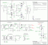
In reference to the EL Cheapo B2 power:
I sure would like someone to do some measurements and proofs that putting those diodes in front of the 100 Ohm resistors performs any useful function.
If those diodes ever turn on and off, then that is a transient.
Drums and Cymbals do transients.
Amplifiers are not supposed to create their own transients.
Just double the 100 Ohm resistors to 200 Ohms, and you will get the same B2 Voltage.
0.006A x 100 Ohm = 0.6V.
And the RC of 200 Ohms and 104.7uF will reduce the ripple by 2, versus RC of 100 Ohms and 104.7uF. No transients created by a resistor.
Last edited:
If you put a standby switch between the first cap and second cap, you better be sure that it is a resistor between the first cap and second cap (CRC).
If it is a CLC, the switch becomes a mini arc welder if you ever make the mistake of opening the standby switch after the amp is on and warmed up.
If it is a CLC, the switch becomes a mini arc welder if you ever make the mistake of opening the standby switch after the amp is on and warmed up.
kodabmx,
Just make sure that the maximum unloaded DCV on all the capacitors all the way down the CLCRCRC chain are all rated for Lots of volts.
You can not count on enough voltage drop in all the Rs, when the first cap is charged to 1.414 times the RMS (with the output tubes current draw is at zero, "out of the circuit").
I have seen voltage ratings that are too low on 'downstream' caps, time and again in schematics that use that kind of 'standby' circuit.
Bad combination.
Last edited:
I don't use a it as a standby, I use it as a cut off for if the bias supply fails. I agree. Every cap in the system should be rated for at least the unloaded power supply voltage.
kodabmx,
Aha, that IS a good idea.
None of us are fast enough at a toggle switch, even if it is on the end table, let alone across the room.
Aha, that IS a good idea.
None of us are fast enough at a toggle switch, even if it is on the end table, let alone across the room.
A relatively simple solution to tube amp protection, should an issue happen, is to impliment a sensing system for current draw - an overload would open the power relay.
In a CLC/CRC pi filter it's easy.
The sensing system across the L or R monitors the voltage drop across it, tripping if beyond maximum current needed.
In a CLC/CRC pi filter it's easy.
The sensing system across the L or R monitors the voltage drop across it, tripping if beyond maximum current needed.
I think you are all losing track that he doesn't know where to measure voltages... is this a good idea....
Hi All, Please forgive me, I did not for some reason realize all the responses that were sent! Thank you! Tried the direct to power idea, not so successful. It looked like some kind of Tesla coil in a scifi movie... I'll open it up and check what cap ratings are. Thanks again!
- Home
- Amplifiers
- Tubes / Valves
- 5U4 Arcing - thoughts???