George may have some Heavy Iron on hand
Actually, its the opposite extreme....the cheapest isolation transformer that Mouser carries, $15.81 feeding 4 X $1 tubes through a $4 OPT.
These guys are not 1:1 the secondary has more turns than the primary to provide 120 volts at rated load. With the little 4 watt amp cranked to where IT screams (not enough power to make any tube scream), the secondary voltage is 134 volts, providing 165 volts at full tilt.
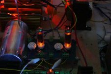
OK, that amp runs a pair of 32ET5's and 4 watts was all I could squeeze out of it. Much to my surprise, I plugged a pair of 32ET5's into my test board, and fed them a bit more voltage......the result KABOOM.....nope, these guys didn't even glow red YET.
I had to go somewhere just when the fun was starting.....25 watts at 5% THD and 35 watts at 12% THD, all on 340 volts plate and 150 volts screen. The wimpy cathodes do something that may prove interesting for a guitar amp. These tubes don't slam into clipping, they ease into it over a 10 watt range. The top and bottom of the wave just gets compressed, more and more until clipping eventually becomes obvious. Maybe there is hope for those 6AQ5's after all. More testing tomorrow.
What output transformer impedance. Certainly not one of those 70V transformers. Oh wait, you probably have for in parallel. 😉
Sorry, I should have stated that. I am currently using a 6600 ohm OPT which I commonly wire for 3300 ohms. It works decently either way. So far all of the 7 pin tube experiments have been done with 6600 ohms since the 50C5's expressed distaste for 3300 ohms.
The OPT is an "80 VA @80 Hz" guitar amp OPT that I bought lots of a long time ago. I got them cheap so I use them any time I do an experiment that could end badly. I set one on fire 15 to 20 years ago and recently severely magnetized one. I am now using the magnetized one after successfully degausing it.
The OPT is an "80 VA @80 Hz" guitar amp OPT that I bought lots of a long time ago. I got them cheap so I use them any time I do an experiment that could end badly. I set one on fire 15 to 20 years ago and recently severely magnetized one. I am now using the magnetized one after successfully degausing it.
What output transformer impedance. Certainly not one of those 70V transformers. Oh wait, you probably have four in parallel. 😉
OOps, quoted myself rather than edit my last post.
Sometimes you dig deeper into something only to realize that the data from the previous two days is wrong.....
I decided to really hammer on some 32ET5's since I have about 50 of them. I had already explored 340 volts on the plate (rated for 150) and 150 volts on the screen (rated for 130), so I turned the knob to the right. For several hours I had 400 volts on the plates of a 150 volt tube, saw power levels in excess of 50 watts and NOTHING was glowing.
This is too good to be true, you certainly can't squeeze 50 watts (OK at 14.3% THD) out of these things, I must be doing something wrong. Is there really 40 some odd watts flowing from these tubes? Touching the 120 watt load resistor leads me to believe there is (it's pretty hot)......OK sanity and reality check, hook up a speaker and crank it.
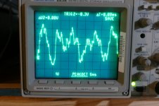
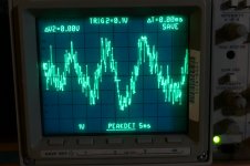
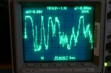
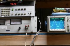
I connected my iPAD to the input, and a $10 thrift store Cerwin Vega speaker that is quite inefficient to the output. I wired my scope across the speaker and played music for at least an hour at full volume. Simple music (Jesse Cook's flamenco guitar) comes through nicely with unclipped peaks touching 50 Vp-p (pic 1). Lets get loud, Trans Siberian Orchestra at full crank, again 50 to 52 volt peaks, unclipped (pic 2). OK crank some modern uber compressed stuff, TNAF Punching in a Dream, clipping happens....a lot! (Pic 3) So if these speakers are 8 ohms, clipping happens at about 43 watts. And nothing blew up.
All of the music sounded great, and the plainly visible clipping on the TNAF music was not as obnoxious as it looks, although quite audible. It was the bass sound from a synth, which is distorted to begin with, and the small satellite speakers couldn't reproduce it faithfully anyway.
My guess was wrong. Squeezing 40+ watts out of tiny tubes is happening because we are well into AB2. This also explains the 100+ watts from some 6L6GB's. The transition from AB1 to AB2 occurs at about 13 watts on 340 volts, and 16 watts on 400 volts. This means that the power seen in previous testing was also helped with some grid current. How much grid current?
That's where things get tricky. I saw excursions over 30 volts at the INPUT OF THE TEST BOARD. The boards have 1K grid stoppers on their BOTTOM side. I need to remove the test board, install a smaller stopper, and make both ends of it accessible for grid current measurements.
Most of us here are not opposed to sticking some silicon into a tube amp, and a mosfet is the easiest way to deal with grid current....my driver boards use mosfet followers to feed the output tube grids.
I will redo my measurements once the board is modified.....I'm guessing this will result in similar or slightly higher power output, or some blown tubes!
Do I really want to feed these tubes (32ET5) more than 400 volts?
I decided to really hammer on some 32ET5's since I have about 50 of them. I had already explored 340 volts on the plate (rated for 150) and 150 volts on the screen (rated for 130), so I turned the knob to the right. For several hours I had 400 volts on the plates of a 150 volt tube, saw power levels in excess of 50 watts and NOTHING was glowing.
This is too good to be true, you certainly can't squeeze 50 watts (OK at 14.3% THD) out of these things, I must be doing something wrong. Is there really 40 some odd watts flowing from these tubes? Touching the 120 watt load resistor leads me to believe there is (it's pretty hot)......OK sanity and reality check, hook up a speaker and crank it.
I connected my iPAD to the input, and a $10 thrift store Cerwin Vega speaker that is quite inefficient to the output. I wired my scope across the speaker and played music for at least an hour at full volume. Simple music (Jesse Cook's flamenco guitar) comes through nicely with unclipped peaks touching 50 Vp-p (pic 1). Lets get loud, Trans Siberian Orchestra at full crank, again 50 to 52 volt peaks, unclipped (pic 2). OK crank some modern uber compressed stuff, TNAF Punching in a Dream, clipping happens....a lot! (Pic 3) So if these speakers are 8 ohms, clipping happens at about 43 watts. And nothing blew up.
All of the music sounded great, and the plainly visible clipping on the TNAF music was not as obnoxious as it looks, although quite audible. It was the bass sound from a synth, which is distorted to begin with, and the small satellite speakers couldn't reproduce it faithfully anyway.
Are you driving them in Class AB or beyond? ..... at what point they transition from AB1 to AB2. My guess is that there isn't much AB2 happening, if any.
My guess was wrong. Squeezing 40+ watts out of tiny tubes is happening because we are well into AB2. This also explains the 100+ watts from some 6L6GB's. The transition from AB1 to AB2 occurs at about 13 watts on 340 volts, and 16 watts on 400 volts. This means that the power seen in previous testing was also helped with some grid current. How much grid current?
That's where things get tricky. I saw excursions over 30 volts at the INPUT OF THE TEST BOARD. The boards have 1K grid stoppers on their BOTTOM side. I need to remove the test board, install a smaller stopper, and make both ends of it accessible for grid current measurements.
Most of us here are not opposed to sticking some silicon into a tube amp, and a mosfet is the easiest way to deal with grid current....my driver boards use mosfet followers to feed the output tube grids.
I will redo my measurements once the board is modified.....I'm guessing this will result in similar or slightly higher power output, or some blown tubes!
Do I really want to feed these tubes (32ET5) more than 400 volts?
Attachments
Ok you convinced me. I think I should look at AB2 in the near future. You can't be the only one having fun.
Amazing results. Leo Fender would have been green with envy at your ability to squeeze enormous amounts of power from dirt-cheap valves!...I rewired the OPT for 6600 ohms.
...so 340 volts it is. I didn't readjust the bias, just nudged the screen voltage down a bit to keep the current around 15 mA per tube. It was 106 volts. Max power was just over 30 watts
<snip>
...so each tube's plate is eating 8.8 watts. The screen current is 7.5 ma from 106 volts, which is .75 watts. Again nothing glowing inside except those 7.5 watt heaters after 15 minutes of cook test.
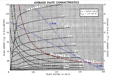
I was really curious what this recipe (106V screen, 340V anodes, 15 mA idle, 6.6k Raa transformer) would look like in a traditional load-line plot. So I went ahead and plotted it.
I started with data-sheet curves for 110V on the screen grid, which is at least somewhat close to the actual 106 V.
Assuming 6.6k is the end-to-end impedance of the output transformer, the load seen by each valve around idle should be 3.3k. Idle current is 15 mA, so at anode currents of more than 30 mA, the second valve should turn off, and the working valve will now see a 1.65k load impedance.
The resulting plot is a head-scratcher for me, because it is so far from reality! George's measured numbers tell the truth: in practice, a 50C5 is happy with these operating conditions. But my load-line plot looks so far above the maximum dissipation curve that it seems like a terrible mistake.
Incidentally, from the load line, I would only expect 12 watts RMS, mainly because a lot of voltage seems to be lost in the valve on negative peaks (the anode can't drop below 120V or so). Clearly, this wasn't happening in reality, since George measured 30 watts output, not 12 watts. This probably has something to do with driving the valves into AB2 mode, creating new curves above the topmost Vgk=0 curve on the datasheet, and so allowing the anode voltage to drop much lower than 120 V.
For what it's worth, the "no more than 12 watts in AB1" seems to agree fairly well with what George reported - that AB2 begins above 13 watts.
It's all very interesting, and provides a lot of food for thought. (And one of those thoughts is that it would be quite nice to have a couple of variable high voltage DC power supplies!)
-Gnobuddy
Attachments
All experiments done today used a pair of 32ET5's into a 3300 ohm load. B+ was 340 or 400 volts, G2 was 150 volts and the OPT is 6600 ohms. Idle current is 12.5 of 15 mA per tube.
I rewired the board so that there are 100 ohm grid stoppers on the top side of the board in place of the 1K ohm on the bottom. This makes it possible to put a scope probe on both ends of the resistor. One of my old scopes has a way to do a differential measurement, thus measuring the voltage across the resistor to determine the grid current.
The 32ET5 when running on 400 volts and being driven to clipping sees 15 mA of grid current on peaks. It does this at the +15 volt peak of the sine wave drive. This means the control grid dissipates 225 MILLIWATTS for a brief instant when the tube is driven to clipping. No grid is going to burn out here.
The reduced grid stopper removed the soft clip seen previously. These tubes now clip like most other tubes. The rising distortion once entering the grid current region is gone too.
Enclosed is a spreadsheet of two test runs. The first is at 340 volts B+ with the idle current set as 15 mA per tube. This gives the lowest distortion within a reasonable plate dissipation. The tubes see about 9.5 watts of dissipation when pushed hard at this voltage. There seems to be no issue at this level. The plate is the same size as the 6AQ5's 10 watt plate. I have not yet found the power level needed for red glow. The screen dissipation hits 1.6 watts when the amp is pushed to 30 watts out. It goes way up when pushed harder. Attempting to hit 35 watts results in a glowing red screen grid and 40 mA screen current per tube.
The second test run extracts 40 watts from the same tubes by turning the B+ up to 400 volts, and lowering the idle current to 12.5 mA per tube to reduce idle dissipation. I ran the tests, then set the generator for 40 watts output (slight clipping on the top of the wave) and left it for 1 hour while I made this spreadsheet. The tubes were dissipating about 13.5 watts each, yet nothing was glowing, so I took pictures. The shot in the dark is at 40 watts output after over 1 hour of continuous operation. The yellow "Sylvania" paint is still yellow. I have been able to turn it brown within a day by extracting 100+ watts from a pair of 13GB5's. Anyone ever see blue glow on the glass of a cheap radio tube?
The 40 watt test is probably a bridge too far, but it proves the feasibility of 30 watts on 340 volts. I can see AMP 1.5 becoming AMP 1.6 although I'll leave the original alone, and make a new one.
That's something that I need to measure.
After taking a few more measurements on the 32ET5, I will revisit the 50C5, but I think wimpy tubes may hamper progress. If that's the case, I will rewire for 50B5's and 6AQ5's (same pinout). It would be interesting to see if the 6AQ5 will respond to AB2 like the 32ET5's do.
I rewired the board so that there are 100 ohm grid stoppers on the top side of the board in place of the 1K ohm on the bottom. This makes it possible to put a scope probe on both ends of the resistor. One of my old scopes has a way to do a differential measurement, thus measuring the voltage across the resistor to determine the grid current.
The 32ET5 when running on 400 volts and being driven to clipping sees 15 mA of grid current on peaks. It does this at the +15 volt peak of the sine wave drive. This means the control grid dissipates 225 MILLIWATTS for a brief instant when the tube is driven to clipping. No grid is going to burn out here.
The reduced grid stopper removed the soft clip seen previously. These tubes now clip like most other tubes. The rising distortion once entering the grid current region is gone too.
Enclosed is a spreadsheet of two test runs. The first is at 340 volts B+ with the idle current set as 15 mA per tube. This gives the lowest distortion within a reasonable plate dissipation. The tubes see about 9.5 watts of dissipation when pushed hard at this voltage. There seems to be no issue at this level. The plate is the same size as the 6AQ5's 10 watt plate. I have not yet found the power level needed for red glow. The screen dissipation hits 1.6 watts when the amp is pushed to 30 watts out. It goes way up when pushed harder. Attempting to hit 35 watts results in a glowing red screen grid and 40 mA screen current per tube.
The second test run extracts 40 watts from the same tubes by turning the B+ up to 400 volts, and lowering the idle current to 12.5 mA per tube to reduce idle dissipation. I ran the tests, then set the generator for 40 watts output (slight clipping on the top of the wave) and left it for 1 hour while I made this spreadsheet. The tubes were dissipating about 13.5 watts each, yet nothing was glowing, so I took pictures. The shot in the dark is at 40 watts output after over 1 hour of continuous operation. The yellow "Sylvania" paint is still yellow. I have been able to turn it brown within a day by extracting 100+ watts from a pair of 13GB5's. Anyone ever see blue glow on the glass of a cheap radio tube?
The 40 watt test is probably a bridge too far, but it proves the feasibility of 30 watts on 340 volts. I can see AMP 1.5 becoming AMP 1.6 although I'll leave the original alone, and make a new one.
a lot of voltage seems to be lost in the valve on negative peaks (the anode can't drop below 120V or so)
That's something that I need to measure.
After taking a few more measurements on the 32ET5, I will revisit the 50C5, but I think wimpy tubes may hamper progress. If that's the case, I will rewire for 50B5's and 6AQ5's (same pinout). It would be interesting to see if the 6AQ5 will respond to AB2 like the 32ET5's do.
Attachments

I'm a little confused, the OPT is now wired for 3300 ohms anode-to-anode? So each valve sees 1650 ohms in the class-A (less than 30 mA current change) part of the cycle, and 825 ohms in the class-B part (more than 30 mA swing)?All experiments done today used a pair of 32ET5's into a 3300 ohm load. B+ was 340 or 400 volts, G2 was 150 volts and the OPT is 6600 ohms.
Idle current is 12.5 or 15 mA per tube.
Or is it 6600 ohms anode-to-anode, 3300 ohms per valve in class A, and 1650 ohms per valve in class B?
I was thinking (and you hinted at the same thing) that the soft clip (with the 1k grid stoppers) might be just the thing for a "touch sensitive" blues or blues-rock amp. I think that's worth investigating!The reduced grid stopper removed the soft clip seen previously.
Well, that explains a lot! The weird thing is that the RCA datasheet I'm looking at says 5.4 watts rated max plate dissipation for the 32ET5!The plate is the same size as the 6AQ5's 10 watt plate.
I'm used to manufacturers overestimating the power handling ability of their products, not grossly understimating it!
Would you suggest using slightly bigger screen grid resistors to safely limit screen grid power dissipation?The screen dissipation hits 1.6 watts when the amp is pushed to 30 watts out. It goes way up when pushed harder.
Attempting to hit 35 watts results in a glowing red screen grid and 40 mA screen current per tube.
Or perhaps the bigger 1k grid stoppers (and maybe some clamping zeners too) could be used to keep a guitar from pushing the output power beyond 30 watts?
I thought the 50C5 and 32ET5 were essentially the same guts in the same bottle with a different heater - am I wrong? Comparing the two RCA datasheets shows only rather minor differences in a few parameters that shouldn't affect power handling ability (for instance, gm is 7500 for the 50C5, 5500 for the 32ET5. Suggested load is 2500 ohms for the 50C5, 2800 ohms for the 32ET5 - barely 10% higher.)After taking a few more measurements on the 32ET5, I will revisit the 50C5, but I think wimpy tubes may hamper progress.
Or perhaps you classify both the 50C5 and 32ET5 as wimpy? Now that you've shown these little 7-pin bottles can put out 30 watts (matching a quartet of 6V6s!) I don't know if we can call them "wimpy" any longer!
-Gnobuddy
I was thinking (and you hinted at the same thing) that the soft clip (with the 1k grid stoppers) might be just the thing for a "touch sensitive" blues or blues-rock amp. I think that's worth investigating!
And then there are people that consider amps that transition from clean to dirty with a sharp transition as being "touch sensitive". The idea is that you can play clean and get into dirt by playing just a bit harder. I found that odd.
Or just don't jack up the voltage as much?Would you suggest using slightly bigger screen grid resistors to safely limit screen grid power dissipation?
Or perhaps the bigger 1k grid stoppers (and maybe some clamping zeners too) could be used to keep a guitar from pushing the output power beyond 30 watts?
Yes but what can he get out of a 6V6? I had a thought. If the grid and screen being driven hard I wonder if running at this level in a combo amp would have any effect on the reliability.One more thought. I guess now there will be a run on 32ET5's.Or perhaps you classify both the 50C5 and 32ET5 as wimpy? Now that you've shown these little 7-pin bottles can put out 30 watts (matching a quartet of 6V6s!) I don't know if we can call them "wimpy" any longer!
-Gnobuddy
I'm a little confused, the OPT is now wired for 3300 ohms anode-to-anode?
Sorry, the dummy was typing late at night after his brain had already gone to sleep. All testing was done at 6600 ohms.
the soft clip (with the 1k grid stoppers) might be just the thing for a "touch sensitive" blues or blues-rock amp. I think that's worth investigating!
Yes, slamming abruptly into hard clipping might be OK for somebody, but I'm not sure who. This looks like another tweaker's "knob" to turn. More experiments will be needed. See the screen grid answer.
the RCA datasheet I'm looking at says 5.4 watts rated max plate dissipation for the 32ET5!
My Sylvania sheet says 5.5. These tubes were designed and only specified for SE class A amps in cheap radios. The recommended operation point is 3.3 watts. The 50C5 has the same plate and it's recommended operation point is 5.4 watts. Both of these were at 110 volts on the plate. The radios that I destroyed as a kid in the 60's produced about 125 to 130 and about 150 when a teenage kid wires a silicon diode across the rectifier tube. They are strong tubes. The 35W4 rectifiers however were not.
Would you suggest using slightly bigger screen grid resistors to safely limit screen grid power dissipation?
The screen definitely must run far below the plate voltage. Screen current shoots up when the plate voltage dips below the screen. This becomes apparent when the amp is pushed to extreme power levels. Screen currents over 40 mA per tube on AVERAGE have been seen. The peaks must be stupid high. The tubes WILL fail if subjected to this repeatedly. Long term operation below the screen current corner doesn't seem to be an issue, so we need to protect the screen. Having the screen regulated is important in a HiFi amp where low distortion at all power levels is important. We don't necessarily need or want that here. Ordinary resistors may be sufficient say from a 170 volt supply to feed the screens.
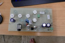
I put the schematic to my 4 watt amp in post # 31. It uses 32ET5's on 170 volts. I will start with a similar design for the 340 volt version, although a bigger power transformer may be needed. The schematic of the 5 tube amp (also in post #31) shows how to get 170 volts and 340 volts at the same time from an isolation transformer.
Look at the schematic of the power supply / output section. The OPT is fed directly from raw B+. The 47 uF filter cap and 47 ohm resistor were chosen to make the little Triad N-68X happy. It gets pretty warm with those values but it got hot with no resistor and a 100uF cap.
The screen grids and the preamp section are both fed from a 2.7 K resistor and a 27 uF cap. Each screen grid has an unbypassed 620 ohm resistor. These 4 components all interplay to determine the sag, sustain and touch sensitivity of the amp. I spent several days tinkering with just these 4 parts. They needed to be messed with again every time I tinkered with the pentode input stage. There is another 27 uF downstream in the preamp B+ chain also that has some effect.
The B+ on the output tubes is currently 165 to 170 volts whether idling or cranked. The screens are at 125 V idling, and 110 V cranked. The preamp sees 128 volts at idle and 115 cranked. These are all contributors to touch sensitivity and sustain. The B+ caps control the timing. Ideally you would want a big cap at the OPT to kill hum, then tweak the two 27 uF caps for a sharp attack that sags and recovers as the note dies. To large of a cap value makes the amp sound sluggish.
I plan to boost the B+ to the OPT only, and still run everything else from a 170 volt supply. I want to test swapping the two preamp stages too. Of course all plans may change once I start playing with it.
I thought the 50C5 and 32ET5 were essentially the same guts in the same bottle with a different heater
There are some differences. The 50C5 has a 7.5 watt heater, and the 32ET5 has a 3.2 watt heater. On paper the 32ET5 should be wimpy in the emission department. In practice I have no problem over-ranging my 200 mA cathode current meters. The 50C5 is from the mid 50's, and the 32ET5 is from the early 60's. The cathode coating compound went through several improvements around that time period primarily to feed the needs of the sweep tubes in constantly growing TV set screens. The 50C5 has a higher Gm and its curves reach 140+ mA with 0 volts on the grid. The 32ET5 barely reaches 100 mA at 0 volts. Neither have positive grid voltage curves. AB2 can be an equalizer by stretching more power out of a tube IF it's cathode has sufficient emission.
I think wimpy tubes may hamper progress. I don't know if we can call them "wimpy" any longer
I was referring to the collection of 50C5's that I have. I found another one, and tossed the tube with the open heater. I still have 5 total. One is NOS and clearly outshines all the others. The 4 other tubes are well used, and somewhat weak in the emission department, thus "wimpy." I can and will retest them, but won't believe the data until I run some NOS 50B5's, which require socket rewiring. The 50B5 and the 6AQ5 have the same pinout......my opinion of the 6AQ5 could change once I test it in AB2. I hope so.....I have LOTS of them.
these little 7-pin bottles can put out 30 watts (matching a quartet of 6V6s!)
I can easily get 30 watts from a pair of 6V6GT's.
a lot of voltage seems to be lost in the valve on negative peaks (the anode can't drop below 120V or so) .....That's something that I need to measure.
The amp is being tested with 340 volts of B+, same conditions as before (6600 ohms). At 30 watts output the plate is swinging from 40 volts to 640 volts.
I guess now there will be a run on 32ET5's.
They have been on the dollar list forever. There were thousands available when the HBAC was active. I don't know now. There are probably several other common radio tubes that might do this too. Right now I'm about to stuff some 60FX5's into the test board. They have a much higher Gm and were designed for cheap stereo record players. One tube per channel driven directly from the ceramic phono cartridge.
A quick test (still at 340 volts) of the 60FX5's show that they are different from the previously tested tubes. The Higher Gm makes each tube quite different from the next, and it took 6 tubes to find something resembling a pair. They really didn't like 150 volts on G2, so I turned it down to 130. The G2 current was still much higher than the 32ET5. Max power was 26 watts, but the distortion was lower than the 32ET5, staying in the 1% range until hitting clipping at 26 watts.
I stuck the best combination of 50C5's in the board. This is a NOS Sylvania paired with a crusty old GE that has half it's getter gone. Max power with 130 volts on G2 was 25 watts, but 30 watts returned with 150 volts. The old GE is indeed weak since the currents became quite unbalanced as the power is increased.
I then paired an old Sylvania with the NOS Sylvania with the socket positions reversed. The imbalance was a little better, as seen in the distortion and current numbers. The data shows the NOS tube runs away from the others at higher power output.
Within tube to tube variation the 50C5's perform exactly the same as the 32ET5's.
I will rewire for 50B5 / 6AQ5 now.
Attachments
I ran a quick test with 50B5's and saw that they were indeed like 50C5's. Didn't take the usual data since I really wanted to find an application for these.....
I said that I had LOTS of 6AQ5's!
Initial testing on 340 volts revealed a brick wall at 20 watts with AB2 happening. Trying different combinations of screen and bias got me to 22 watts. So, the next obvious thing is to turn up the B+. 400 volts brought 30 watts AND a pale red spot on one plate after a 10 minute heat soak. More experiments will dig deeper, but this means trying different load impedances.
A rough calculation shows that red starts at about 14 to 16 watts of plate dissipation.
Attachments
Last edited:
So just talking out loud, guitar amps are normally set to idle in the range of 60-100% of plate current. Rather than the 50C5's datasheet value of plate dissipation we can give roughly a 10W rating for it. You are running the tubes in P-P about their Class A rated impedance (2.5k) for their 110V spec. (doubled for P-P roughly 5k, higher voltage is better with a higher impedance, the 6.6k is a step in the right direction). So you are idling about 50%, where in many guitar amps they run close to 75-100% dissipation in cathode biased amps. This reminds me on a Harman Kardon running 12AB5's north of 400V.
No real point, just trying to work through the wattage output. So at full power for the voltage and primary impedance you are not really dissipating more than the 10W rating (visual rating going by size) of the plates.
You snuck another post in there without me knowing. I have a fair amount of 6AQ5's also. Carry on.
Last edited:
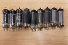
What is a 6AQ5? All of these have the numbers 6AQ5.. on them.
The three on the left are also numbered 6005. They are GE made, and have plates that are about 20% smaller that "normal" 6AQ5's. When tested on 400 volts they make 23 watts. They don't glow red, they just won't go past 23 watts.
The next pair are Sylvania 6005 / 6AQ5W, the exact same number found on the clear glass GE's. They however have no problem cranking out over 35 watts without glowing. I now have the third set of these sitting in the hot seat cranking out 36 watts @ 3% THD in the exact same setup as the 23 watt "wimps." They have been in there for over 30 minutes.
The black plate RCA 6AQ5A's are another winner, two pairs made 35 watts for 10 minutes each....no glow.
The grey GE's on the far right however do glow at 30 watts. Note the tab on the plate in the tube on the right. That's what glows.
There are several more different "6AQ5's" that I haven't tested, but id does seem that the 15 watt limit is bogus when AB2 is allowed.
Attachments
I guess the limiting factor on the low buck amp is the 70V transformer. Hey, any idea what it will put out before puking?
Hey, any idea what it will put out before puking?
I guess there is one way to find out......Hey they are on sale now for $3.98
70V 10W Speaker Line Matching Transformer
The issue is that it's impedance is probably to low for these tests. I can't remember, but I think it was in the 3K range when I tested it. It wouldn't surprise me that a pair of 32ET5's would only make 4 watts on 170 volts without AB2. Maybe the tubes and transformer together are only good for 4 watts. I never pursued more power because its really loud when turned all the way up.
I have a few of them here, so I'll figure out how to test one.
This afternoon's fun was attempting to blow some 6AQ5's. I found one that has most of its cathode coating rattling around loose inside the glass. I figured that it would be good for some fireworks on 400 volts, but there were no sparks, just weak and distorted output.
I did however find that there are two kinds of tubes with the number 6AQ5 on them. Those that make under 25 watts on 400 volts, and those that make over 30. The low power flavor has a smaller plate. I put them aside and proceeded to torture several pairs of the big boys at absurd power levels. 40 watts output brings tube killing screen grid current, but I made some quick measurements and cut power. Distortion at 40 watts is in the 10 to 15% range and severely clipped. 35 watts however comes at 3 to 5% distortion and 14 to 15 watts of tube dissipation against a 12 watt spec. Screen dissipation is 1.5 to 1.9 watts against a 2 watt spec. The efficiency is still 8 to 10% lower than the 32ET5 / 50C5.
I ran several pairs for 30 to 60 minutes at 35 watts , and only the tab on the GE tubes showed a faint red glow.
Would I recommend making a 6AQ5 amp on 400 volts, probably not, but this testing proves that the 250 volt spec has some margin, and more than 10 watts are possible. Where Is the line? I don't know yet.
I spent several hours with a BIG box full of tubes and didn't blow any up. That's far better that my previous experience with these same tubes....I have owned these for over 20 years.
1st round of experiments.
I sorted these out of probably a few thousand 6AQ5's that were on their way to a landfill when someone found mercury inside some rectifiers and stopped the bulldozer that was tearing down the building with the tubes inside. Many were broken or so corroded that the pins would fall off when touched. I had fun blowing some of them up while sorting.
2nd round of experiments
I mads a few HiFi and guitar amplifiers that used the 6AQ5's and other tubes that I have lots of. None were particularly interesting, and I had plenty of more interesting tubes to play with, so these got shelved. There was a little 4 tube HiFi amp that used a pair of 6AQ5's and a pair of 6AU6's that sounded nice, but got lost in the shuffle. I have seen it here somewhere, but I don't know where it is now.
3rd round.
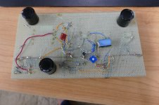
The HBAC brought the 6AQ5's, 6AU6's, 6AK5's and a few others out of the warehouse for prototyping. The first iteration of the 32ET5 amp actually used a pair of 6AQ5's, a 6AU6, and a pair of 6AQ6's. The cost cutting brought out the dollar tubes and isolation transformers. I have found that first breadboard, though it's pretty hacked up.
Maybe it's time for round 4?
Attachments
I guess there is one way to find out......Hey they are on sale now for $3.98
I had to laugh when I saw that. Then recalled the cheapest I can get the transformers is $20, ridiculous. I got a few from when we did demo's at work where they were used for their intended PA duty. On the transformers I think if you have a 1/2W tap you use that for one plate, the 1W tap for the supply and the common for the other plate. Looked it up, this is for a 4W version. I may have to find one for a 6AK6 P-P spring reverb.
For a 70 volt line transformer (actually 70.71 volts) having 4, 2, 1, 0.5 and 0.25 watt taps, this gives primary impedances of 1250, 2500, 5000, 10,000 and 20,000 ohms respectively. Starting from the primary common lead, the number of turns increases by √2 every tap. Hence, the number of turns doubles every two taps.
Shame they do not have more inductance.
All this talk about 6AQ5's made me look up the few that I have.
Sure enough, only one RCA 6AQ5.
The others are French SFR 6005/6AQ5W, shorter plate looking like the GEs but with the plate ridges flattened.
The SFR logo is etched on the glass, together with the type numbers.
I wonder why the French used US type numbers instead of the European EL90 name. Could it be different specs?
Looking around datasheets, I find different max disspiation (10-12W) and max cathode current (55-67mA)
- Status
- Not open for further replies.
- Home
- Live Sound
- Instruments and Amps
- 5E3 Blackface Single End Amp