Mostly because I had unused transformers at home and was looking for simple design with minimal parts.Is there any reason you really would like to use a transformer? It does hugely increase cost,
15k:150 would have a 10:1 stepdown ratio.
This does look interesting, perhaps for another project in the future 🙂This is a circuit I was working on a while ago. I never built it, so it's just a thought experiment at this point.
It does load down into a 32 ohm load. While the THD is a super-low 0.02% at 1V out into a 300 ohm load, it worsens to 0.08% with 10mW into a 32 ohm load. However, that's probably hi-fi enough for a tube amp with low impedance cans since 10mW will probably make you deaf with those on.
Yes, the plan is to use 10K-25K pot.An issue I completely forgot about is the triode's input capacitance. The 5842 has appreciable input C due to Miller effect. It's Cgp is probably about 1pF + 0.7pF for strays, so expect the input C to be up around 100pF. If you're using a 100k volume control, its maximum output impedance is going to be 25k ohms. An RC of 25k and 100pF = F3 of 63.6kHz.
I like to see less of a high frequency roll-off from the volume control, so I'm using a 25k stepped attenuator in the headphone amp. The 12GN7A-triode has input C of about 100pF and gain of roughly 25. The max output resistance of a 25k pot is about 6.25k ohms, which means the F3 at high frequency will be about 250kHz, which is high enough to not matter. I originally had a 100k pot in the amp, but I could hear a definite improvement in the high frequencies when I replaced that with the 25k pot -- even with my tired old ears.
Got it, the Sowter seems like a viable option then, at high(ish) cost and size.As long as the primary inductance stays up near 40H with 25mA standing current across its primary, my guess is that this Sowter line transformer should work nicely. It does look like a high quality transformer.
It looks like there are a few high quality non-gapped transformers available:Before I abandon this project is it worth considering a Parafeed design?
- Sowter 8665 -- https://www.sowter.co.uk/specs/8665.php (Pete millet used it here http://www.pmillett.com/ecc99_srpp_headphone_amp.htm)
- Lundahl LL1930
- Jensen JT-10K61-1M
- Cinemag have a few.
These would be smaller (mostly cheaper) than the gapped SE. I don't mind the AC coupling capacitor..... but need help with general schematic/approach and pros/cons of CCS vs plate choke.
Thoughts?
the Sowter seems like a viable option then, at high(ish) cost and size.
Any single-ended output transformer is going to be large and expensive, because it needs to have a relatively large primary inductance, yet it also needs to be air-gapped so it can withstand current on its primary, but the air gap reduces the primary inductance, so now the transformer needs to be made larger to increase the inductance, but now the transformer is larger so more wire needs to be wound around the core, so now there's more capacitance between windings, which degrades the high frequency performance... so now what do you do?
Oh. Parafeed.
Sorry, now we're opening another can of worms. This could go on forever.need help with general schematic/approach and pros/cons of CCS vs plate choke.
Isn't this fun?
Why is a (gapless) transformer stuck after a capacitor better than a capacitor?
Yes, you are right, there are many possibilities and to get a result the direction can't be constantly changed.
Summarizing (for myself mostly):
If I stick to the initial requirements, I have a working direction for a simple amp with the existing Edcor 5K:16 OPT.
I learned a good operating point (Vp=150V, Rk=~60ohms, Ia=25mA), and that not much was to be gained with UltraPath (atleast in this circuit).
The two downsides (from my perspective) to this result is the the limited LF extension and power (although mostly theoretical as its sufficient for most headphones).
How can these potentially be addressed ?
Which leaves the only unexplored direction (from my perspective) parafeed, which seems like it can address both issues, since transformers can be had with higher inductance and lower turns ration, and the required capacitor is smaller.
There are also a few quality headphone designs that are built this way such as the Bottlehead Mainline and ECP Torpedo.
But I'm still a super beginner, so rely heavily on your expertise.
Summarizing (for myself mostly):
If I stick to the initial requirements, I have a working direction for a simple amp with the existing Edcor 5K:16 OPT.
I learned a good operating point (Vp=150V, Rk=~60ohms, Ia=25mA), and that not much was to be gained with UltraPath (atleast in this circuit).
The two downsides (from my perspective) to this result is the the limited LF extension and power (although mostly theoretical as its sufficient for most headphones).
How can these potentially be addressed ?
- "Better" transformer -- more cost, size and weight, but practical option.
- NFB - not enough gain for this
- OTL (see below)
- Parafeed
I don't want to pursue OTL for 2 main reasonsWhy is a (gapless) transformer stuck after a capacitor better than a capacitor?
- If the output capacitor fails closed there is ~B+ on the headphones (or is this not the case?)
- I would prefer the amp to work with a variety of headphone impedances, which would require very large caps that could also be expensive.
Which leaves the only unexplored direction (from my perspective) parafeed, which seems like it can address both issues, since transformers can be had with higher inductance and lower turns ration, and the required capacitor is smaller.
There are also a few quality headphone designs that are built this way such as the Bottlehead Mainline and ECP Torpedo.
But I'm still a super beginner, so rely heavily on your expertise.
Time for some research...
https://www.tubecad.com/2014/09/blog0308.htm
https://www.head-fi.org/threads/a-very-simple-single-ended-parafeed-design.824225/
https://www.hifiwigwam.com/threads/parafeed-valve-amps.108512/
http://tubelab.com/articles/ideas/single-ended-output-stages/
There's more, but that's a start.
https://www.tubecad.com/2014/09/blog0308.htm
https://www.head-fi.org/threads/a-very-simple-single-ended-parafeed-design.824225/
https://www.hifiwigwam.com/threads/parafeed-valve-amps.108512/
http://tubelab.com/articles/ideas/single-ended-output-stages/
There's more, but that's a start.

This article takes you through an interesting design that is basically what you're proposing, except made with a 6S45P-E triode (high mu, extremely high gm, therefore low rp -- exactly what you want here).
https://wtfamps.com/papa-rusa-headphone-amplifier/

Since it uses a MOSFET for the CCS, it won't be terribly expensive. The OPT is not expensive either. Probably the only hard to find part will be a really good 4.7uF 400V film cap. But they're around, sometimes surplus.
https://wtfamps.com/papa-rusa-headphone-amplifier/
Since it uses a MOSFET for the CCS, it won't be terribly expensive. The OPT is not expensive either. Probably the only hard to find part will be a really good 4.7uF 400V film cap. But they're around, sometimes surplus.
Thanks, looking.
I have read the previous links you attached, as well as http://diy.ecpaudio.com/p/parafeed-tutorial.html which provided a fairly good summary.
Seems like parafeed with CCS might be the way to go
I have read the previous links you attached, as well as http://diy.ecpaudio.com/p/parafeed-tutorial.html which provided a fairly good summary.
Seems like parafeed with CCS might be the way to go
rongon,
Just use a 4.0 uF 440VAC "motor start" capacitor. Nice metal case, can use an oval mounting bracket, or put it under the chassis. They are rather large, but are nice non-polar caps. I have lots of them.
4 uF and 10k primary takes you down to 3.98 Hz at - 3dB (a lot lower than your headphones go).
Of course, the output transformer will probably not go down to 3.98 Hz, not enough inductance and laminations.
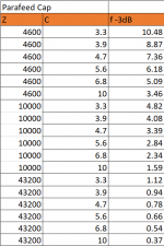
I've been doing some homework for the Parafeed approach.
First, I calculated the reflected load of headphones between 32-300 ohms on the various transformers available:

Next, I measured the AC voltage at the plate with a 1khz signal at 1Vrms and 2Vrms at the common reflected loads, 5k, 10k, 20k, 30k, 47k from the table above. I used 1V as the input to get an idea of gain, and 2V input to see how much voltage would be needed for the CCS with a standard 2V output.
Not listed in the table but THD was significantly worse at the 5K load, which is a bit low at about 2.5X Rp.

Combining the above data, I determined what the theoretical max power output would b with the Sowter and Edcor. The Sowter has taps for 1:6 and 1:12 and the Edcor for 1:8.2 and 1:16.3. The theoretical max power is excessive but not necessarily more than what commercial desktop headphone amps deliver. I could add an L-pad at the output or run at a lower operating point to reduce gain.

For the parafeed cap, seems like anything between 4-6uF should work fine.
With a Zp=4600 fc would be 7-6Hz, at Zp=43K fc is below 1Hz.
I have a few questions regarding incorporating the CCS:
1. Based on 40X gain at higher Z, assuming Vp=150V, B+ then needs to be at 230V, correct? (80V overhead for CCS).
2. Based on the 10M45S datasheet, the series resistor needs to be roughly 100ohms for 25mA constant current. Does Rk need to be the same value as if a CCS wasn't used i.e 60ohms?
3. How to handle mismatched tubes? In the Tubelab SE, there is a 1K trimpot in parallel to Rk to match Vp. If Vp are equal, and the CCS is forcing 25mA, will that also force the same grid voltage (with each tube having slightly different final Rk values?)
Thanks again !!
First, I calculated the reflected load of headphones between 32-300 ohms on the various transformers available:
Next, I measured the AC voltage at the plate with a 1khz signal at 1Vrms and 2Vrms at the common reflected loads, 5k, 10k, 20k, 30k, 47k from the table above. I used 1V as the input to get an idea of gain, and 2V input to see how much voltage would be needed for the CCS with a standard 2V output.
Not listed in the table but THD was significantly worse at the 5K load, which is a bit low at about 2.5X Rp.
Combining the above data, I determined what the theoretical max power output would b with the Sowter and Edcor. The Sowter has taps for 1:6 and 1:12 and the Edcor for 1:8.2 and 1:16.3. The theoretical max power is excessive but not necessarily more than what commercial desktop headphone amps deliver. I could add an L-pad at the output or run at a lower operating point to reduce gain.
For the parafeed cap, seems like anything between 4-6uF should work fine.
With a Zp=4600 fc would be 7-6Hz, at Zp=43K fc is below 1Hz.
I have a few questions regarding incorporating the CCS:
1. Based on 40X gain at higher Z, assuming Vp=150V, B+ then needs to be at 230V, correct? (80V overhead for CCS).
2. Based on the 10M45S datasheet, the series resistor needs to be roughly 100ohms for 25mA constant current. Does Rk need to be the same value as if a CCS wasn't used i.e 60ohms?
3. How to handle mismatched tubes? In the Tubelab SE, there is a 1K trimpot in parallel to Rk to match Vp. If Vp are equal, and the CCS is forcing 25mA, will that also force the same grid voltage (with each tube having slightly different final Rk values?)
Thanks again !!
Attachments
These are wound for 32 or 300 ohm secondaries, 10k, 7k or 5k primaries.
https://edcorusa.com/products/pcw-1...-matching-transformers?variant=41869145112763
https://edcorusa.com/products/pcw-1...-matching-transformers?variant=41236729200827
https://edcorusa.com/products/pcw-1...-matching-transformers?variant=41869145112763
https://edcorusa.com/products/pcw-1...-matching-transformers?variant=41236729200827
The gate-source voltage of MOSFETs varies quite a bit between samples. I've found I always need to use a trimpot for Rset to set the current for the CCS. I'd use a 33 ohm resistor in series with a 100 ohm trimpot, and adjust the trimpot to get 25mA under load. If you use a cathode resistor (bypassed or not) you can use Ohm's Law to figure the current drawn.2. Based on the 10M45S datasheet, the series resistor needs to be roughly 100ohms for 25mA constant current. Does Rk need to be the same value as if a CCS wasn't used i.e 60ohms?
The 5842 Rk will set the grid voltage.
If you want Ip = 25mA with Vp = 150V, what is the grid voltage required? I think it's -1.55V. So...
1.55/0.025 = 62 ohms
The 10M45S Rset (current set resistor) will need to be adjusted-on-test to set the CCS to 25mA.
I believe the CCS will work fine with as little as 50V dropped across the 10M45S (drain to source). Less than that might degrade performance a little, but I think going down to 25Vds would be too low.
If you need 150V at the 5842 plate, with Ip = 25mA its Pdiss will be 3.75W, which should be fine.
With 50V dropped across the CCS, that means you'll want a B+ of 200V.
As always with tubes, voltages 10% off from these will likely make no difference.
Windcrest77's suggestions look good. Having both 32 ohm and 300 ohm taps on the secondary would be great for a headphone amp, covering the two basic headphone types.
6A3sUMMER's suggestion to find a couple of 4uF motor run caps is a good one. Motor run caps are plastic film, not electrolytic. However, motor start caps are almost always electrolytics, so you do not want to use those.
This makes sense. I would have thought the 10M45S had better consistency between units.The gate-source voltage of MOSFETs varies quite a bit between samples. I've found I always need to use a trimpot for Rset to set the current for the CCS. I'd use a 33 ohm resistor in series with a 100 ohm trimpot, and adjust the trimpot to get 25mA under load. If you use a cathode resistor (bypassed or not) you can use Ohm's Law to figure the current drawn.
In the Tubelab SE, there is a trim pot in parallel to the cathode resistor and it is adjusted to reach a target plate voltage, so I think I will use the same approach to to overcome variances between tubes.The 5842 Rk will set the grid voltage.
If you want Ip = 25mA with Vp = 150V, what is the grid voltage required? I think it's -1.55V. So...
1.55/0.025 = 62 ohms
I placed an order for the Sowter 8665, which also had a favorable configuration. If it doesnt work out on this build, I could use it for something else later. I may grab one of those Edcors too just to see if there is any difference.Windcrest77's suggestions look good. Having both 32 ohm and 300 ohm taps on the secondary would be great for a headphone amp, covering the two basic headphone types.
6A3sUMMER's suggestion to find a couple of 4uF motor run caps is a good one. Motor run caps are plastic film, not electrolytic. However, motor start caps are almost always electrolytics, so you do not want to use those.
I've also ordered a 3.9/4.7/5.1uF Solen PP caps for testing in the final circuit, they are fairly small and cheap.
I was wondering if you ever reached a conclusion to this old thread of yours ? https://www.diyaudio.com/community/threads/simple-b-delay-circuit-for-tube-power-amp.195190/
Until the tubes warm up, B+ will be upwards of 250V, exceeding the max ratings for the tube.
Unless, does the CCS also help here by dropping voltage even before the tube has warmed up unlike a resistor?
The gate-source voltage of MOSFETs varies quite a bit between samples. I've found I always need to use a trimpot for Rset to set the current for the CCS. I'd use a 33 ohm resistor in series with a 100 ohm trimpot, and adjust the trimpot to get 25mA under load. If you use a cathode resistor (bypassed or not) you can use Ohm's Law to figure the current drawn.
The 5842 Rk will set the grid voltage.
If you want Ip = 25mA with Vp = 150V, what is the grid voltage required? I think it's -1.55V. So...
1.55/0.025 = 62 ohms
The 10M45S Rset (current set resistor) will need to be adjusted-on-test to set the CCS to 25mA.
I believe the CCS will work fine with as little as 50V dropped across the 10M45S (drain to source). Less than that might degrade performance a little, but I think going down to 25Vds would be too low.
If you need 150V at the 5842 plate, with Ip = 25mA its Pdiss will be 3.75W, which should be fine.
With 50V dropped across the CCS, that means you'll want a B+ of 200V.
As always with tubes, voltages 10% off from these will likely make no difference.
Windcrest77's suggestions look good. Having both 32 ohm and 300 ohm taps on the secondary would be great for a headphone amp, covering the two basic headphone types.
6A3sUMMER's suggestion to find a couple of 4uF motor run caps is a good one. Motor run caps are plastic film, not electrolytic. However, motor start caps are almost always electrolytics, so you do not want to use those.
Thanks for this, it clears up a lot I was wondering about the papa rusa's highish B+ out of the PS. Was hoping to drop less across the ccs than what the schematic delivers using the recommended power transformer.
Can you explain how the 50V headroom for the CCS is determined?
In my tests, with 10K load and above the gain was 40X. I fed both 1Vrms and 2Vrms signals and THD was reasonable, so I assumed that I would need 80V headroom at the CCS (2Vrms X40 => 80V)
I didn't consider the grid voltage though, which is roughly -1.55V.
Is the explanation that the input signal should be limited to 1.55Vrms, otherwise the tube grid will be positive? In that case the headroom should be closer to the 50V mentioned.
The Sowter 8665 transformers arrived today, I'll be testing the parafeed setup within the next few days.
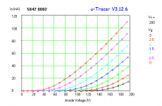
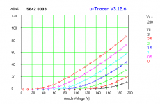
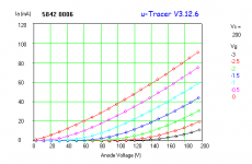
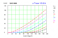
In the meanwhile, I was finally able to finish building a uTracer, a project that was going on for atleast 2 years.
Still learning how to best use this tool, but I tested (8) 5842 tubes I have and the results are pretty interesting.
At Vp=150V and Vg=-1.5V, Ia and mu are all over the place, with Amperex and Ericsson higher than the Raytheon and WE I have.

Another really interesting feature that I didnt know existed, was once the the tube curves are traced, you can enter B+, RL Vg and it will draw a load line and calculate distortion.
In the meanwhile, I was finally able to finish building a uTracer, a project that was going on for atleast 2 years.
Still learning how to best use this tool, but I tested (8) 5842 tubes I have and the results are pretty interesting.
At Vp=150V and Vg=-1.5V, Ia and mu are all over the place, with Amperex and Ericsson higher than the Raytheon and WE I have.
Another really interesting feature that I didnt know existed, was once the the tube curves are traced, you can enter B+, RL Vg and it will draw a load line and calculate distortion.
Attachments
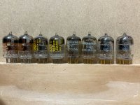
IIRC, the 417 datasheet specifically warns against fixed bias; rather a somewhat positive G1 voltage and cathode resistor big enough to swamp tube-to-tube variation. This variability is the trade-off for too-close grid spacing and high Gm.At Vp=150V and Vg=-1.5V, Ia and mu are all over the place
If you can normalize to same cathode current some of that "all over place" may be reduced. (However I see that some of these tubes are just wound different.)
I recently acquired some 6S45P (6c45π) and D3a which could also work well in the Parafeed setup so I'd like to test and compare them to the 5842 before I build it since they are not pin compatible.
In order to make experimentation easier I want to create this PCB for the plate CCS and grid/cathode adjustments.
One thing I need help with are the trimpots.
For the plate CCS, Rk1 will be a 10ohm resistor in series with the trimpot, to measure current via the voltage drop on the resisitor.
In order to not leave pin 3 floating I am tying pins 2 and 3 so this is effectively a rheostat. This one seems fine.
For the cathode circuit, I am basically copying the Tubelab SE schematic which has a fixed resistor in parallel with a trim resistor.
The purpose is the adjust the cathode resistor to a specific plate voltage.
In the TSE schematic, pin 3 is floating which I read was not optimal (maybe it is shorted in the PCB)
In addition, I have read that rheostats should only be wired in series and not in parallel, so effectively I am unsure if this optimal or I should wire in series like the CCS.
I built something very similar for my son. It’s called Mr Potatohead. I used Altec 15095 OPTs. 150V the plate, 1.5V 40ma LED in the cathode )might have been 1.7 V. Can’t remember exactly, not critical. Cascode Depletion Mosfet CCS, 20mA. Sounds wonderful.This article takes you through an interesting design that is basically what you're proposing, except made with a 6S45P-E triode (high mu, extremely high gm, therefore low rp -- exactly what you want here).
https://wtfamps.com/papa-rusa-headphone-amplifier/
View attachment 1124084
Since it uses a MOSFET for the CCS, it won't be terribly expensive. The OPT is not expensive either. Probably the only hard to find part will be a really good 4.7uF 400V film cap. But they're around, sometimes surplus.
Only real change to the posted schematic would be to return the -be leg of the primary to the cathode (kinda ultra path).
Quality power supply pays dividends. LCLC recommended. One can use a standard choke for the. 2nd L could be conventional ir Tent Labs eChoke (or bread boarded “cap multiplier” as described earlier). Motor run start or DC link caps preferred. Electros also work but with a bit of a change in sound. YMMV.
AC on heaters worked fine. DC on heaters if you are anal retentive.
Grid stoppers on each grid are mandatory 100 ohms or higher depending on one’s RF environment. I also use 100 ohm stopper on the plate for this class of tube.
Whip up a CCS and use the existing series feed OPT as parallel feed as a test/see if you like it.
Most headphones don’t need much gain or much power. The above will drive most with aplomb. Maybe even planar magnetics. ;-)
Have fun!
Caution:
The schematic in Post # 56 is drawn Wrong!
It shows What Not To Do. It does that, but . . .
I hope Newbies do not see that schematic and get the wrong idea, and try to build it.
Yes, I am aware that Western Electric Note 3 says not to do that. But sometimes a schematic sticks in someones head, and they build it.
When do you apply +9VDC on the grid, and 0V on the cathode/filament? . . . (relative voltage).
Only when you want Meltdown.
Or, when the negative on the battery returns to the bottom of a very large cathode self bias resistor,
Or, to the bottom of a CCS to the cathode.
9V Peak Signal on a grid is Good for RF class C amplifiers.
It is not good for Audio.
Just My Opinions
Last edited:
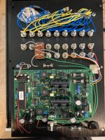
I received the CCS experiment PCB and ran the first tests in the parafeed configuration w/ bypassed cathode resistor. (250V B+, 150 Vp, Ip 20mA)Thanks for the tips @rongon.
I was able to test this today out of parts I had around intended for other projects.
For B+, I had a tomchr's Maida Regulator so was able to dial in arbitrary B+ for testing.
The only test I was able to do had the following parameters:
- Regulated 6.3V DC for heaters
- B+: 173V
- Vp: 170V
- Rk: 100ohms
- V(grid to cathode): 1.8V => 18mA
- 60uF motor run cap for UltraPath connection
- 5K:16 OPT with 33R load resistor
9mW output at 0.58% THD
340mW output at 3.5% THD
The main issue is low frequency roll-off starting at roughly 80hz.
I temporarily removed the UltraPath connection for a 470uF cathode bypass cap and it was better but still rolled off.
Any thoughts which parameters I should tweak try tweaking?
The thread is getting long, so as a recap, I wanted to explore parafeed due to the LF roll-off using the SE opt (not enough inductance).
In Pf, with the Sowter 8665, the LF is basically flat, around 0.5dB down at 20Hz (compared to 80Hz) in the quoted message.
I've experimented with a few Pf caps 2.2/4.7/5.6/8.2uF:
with 2.2uF there is some roll-off, and above 4.7uF there were no further improvements.
There is one unexpected result (to me), and would appreciate some help understanding.
The OPT is configured in the 12:1 ratio, terminated with a 32R resistor, which resulted in mu=30.
Changed the 32R resistor to 100R, mu is closer to 40.
This behavior is what I observed when increasing the load from 5K in the previous SE setup.
This was unexpected, because I was under the impression that the CCS always provides a high impedance to the plate, regardless of whether the secondary is connected to 32 or 300 ohms.... Is this not correct or perhaps I made a mistake in wiring?
- Home
- Amplifiers
- Tubes / Valves
- 5842 headphone amplifier