Re: the power supply, I was just following the schematic here but I think the key difference is that the peak charging current is less relevant when using the diodes vs the 5Y3GT, so either should be fine in my case.
For capacitance multiplier, is a choke necessary? Reading some threads here, isn't that approach as a cost effective approach to a choke?
Point-to-point is a good idea for testing. I think I have all the necessary parts in my bin to test this out.
For plate current, based on the datasheet it seemed like 25mA was the preferred operating point for Class A1?
Re: the power supply, I was just following the schematic here but I think the key difference is that the peak charging current is less relevant when using the diodes vs the 5Y3GT, so either should be fine in my case.
For capacitance multiplier, is a choke necessary? Reading some threads here, isn't that approach as a cost effective approach to a choke?
Point-to-point is a good idea for testing. I think I have all the necessary parts in my bin to test this out.
For plate current, based on the datasheet it seemed like 25mA was the preferred operating point for Class A1?
A capacitance multiplier uses a source follower to approximate a larger capacitance with much less voltage drop than what can be obtained from a simple RC network. I was thinking you could use the choke input filter for its regulation and the capacitance multiplier for its ripple rejection and have a very good power supply with few parts. However, the PSU you've suggested looks like it should work well enough.
A gyrator is a similar circuit that mimics an inductor.
If you use that Ultrapath connection, you'll need to make sure your raw B+ is clean. The Ultrapath cap from cathode to B+ will inject whatever ripple is on the B+ into the cathode of the triode. If the B+ is noisy, that will become a problem.
If you have 160V at the 5842 plate, and 25mA plate current, the grid bias should be about -1.55V (Rk = 62 ohms). Morgan Jones wrote in Valve Amplifiers that when he measured the distortion spectrum of a 5842 for one of his phono preamps, he found that harmonics above the 3rd became more prominent as the bias got too close to 0V. He settled on using a red LED in the cathode to get more like -1.7V grid bias. However, MJ was testing at small signal levels. I guess the way to figure out what sounds best would be to build the circuit and try different cathode resistor values. (That's what I did with my 12HL7/12GN7A headphone amp.)
Vp = 160V and Ip = 25mA would mean the plate dissipation will be 4W, which is right up at the maximum for 5842. You'll be using up the tubes if you do a lot of headphone listening. Perhaps it would be better to back off the plate current a bit to get a 'taller' grid bias? Maybe aim for Ip = 20mA so Pdiss is around 3.2W.
Last edited:
Thanks for the tips @rongon.
I was able to test this today out of parts I had around intended for other projects.
For B+, I had a tomchr's Maida Regulator so was able to dial in arbitrary B+ for testing.
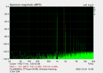
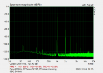
The only test I was able to do had the following parameters:
9mW output at 0.58% THD
340mW output at 3.5% THD
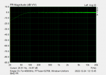
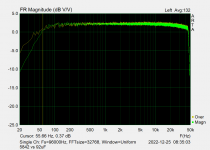
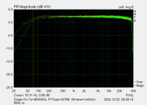
The main issue is low frequency roll-off starting at roughly 80hz.
I temporarily removed the UltraPath connection for a 470uF cathode bypass cap and it was better but still rolled off.
Any thoughts which parameters I should tweak try tweaking?
I was able to test this today out of parts I had around intended for other projects.
For B+, I had a tomchr's Maida Regulator so was able to dial in arbitrary B+ for testing.
The only test I was able to do had the following parameters:
- Regulated 6.3V DC for heaters
- B+: 173V
- Vp: 170V
- Rk: 100ohms
- V(grid to cathode): 1.8V => 18mA
- 60uF motor run cap for UltraPath connection
- 5K:16 OPT with 33R load resistor
9mW output at 0.58% THD
340mW output at 3.5% THD
The main issue is low frequency roll-off starting at roughly 80hz.
I temporarily removed the UltraPath connection for a 470uF cathode bypass cap and it was better but still rolled off.
Any thoughts which parameters I should tweak try tweaking?
Attachments

"Edcor CXSE 5K:16 5W open-frame OPT (I have an unused pair)"
A check of data sheet shows this...
Your result is indicative of its low frequency limitation....
A check of data sheet shows this...
| Frequency Response | 40~20K Hz., <1dBu |
That low frequency limitation is likely to be caused by the OPT's (probably low) primary inductance (Lpri) interacting with the source resistance driving it (rp of the 5842).
5842 rp at your chosen operating points is likely to be about 2k ohms.
To get F3 = 10Hz, the OPT's Lpri will need to be at least 30 Henries.
Do you know what the primary inductance is of your OPTs?
The Lpri of the (very cheap) output transformers I used measure only 8 Hy with a handheld LCR meter, which I figure means the L is more like 15 Hy at low audio frequencies. That's still not a lot of inductance. Therefore, I made sure to run my 12GN7A-triodes 'low and hot' (Ip = 35mA, rp = ca. 1.2k ohms, mu = ca. 35 or so) to maximize low frequency extension. My spud headphone amp is -1dB at around 40Hz, but I'm okay with that for headphone use.
Since the 5842 is going to have slightly higher rp than 12GN7A-triode, your OPT is going to need to have higher Lpri.
Also, what value of Rk did you install? Is it something like 100 ohms? If so, you'll want the time constant of Rk//Ck to be long enough to pass 20Hz or lower without too much attenuation (and increase of rp at low frequencies from negative feedback due to cathode degeneration). If you don't, there may be a bass boost/resonance that causes a steep rolloff below a relatively high frequency. Try increasing the value of Ck to 1000uF or so.
I'm not sure if that's what's happening in your case, but it's my best guess.
PS - If you have some gain to spare, you could increase the bandwidth by applying a bit of negative feedback. 😱
Last edited:
I measured the primary inductance with one of those transistor testers. I wasn't sure what to do with the secondary, left open it measured around 10H, closed with a 16ohm resistor it measured 4H.
I ran a bunch of tests now --
Preliminary results:
-62R measured better than 75R
-Cathode bypass had better low frequency response than UP, small/no difference between 470uF and 1000uF. UltraPath low frequency response was improved with increased capacitance, almost as good as the Cathode bypass.
-175V measured better than 155V but not significantly and may not be worth the extra dissipation
-I'm not sure of the significance but the roll-off of UltraPath measures much "smoother"
I'm re-considering my original plan to buy a pair of Lundahl 2766/30mA which have a primary inductance of 43H.
I've used this CXSE 5W in an EL84 SE amp before and there was no issue with low frequency roll off, likely due to the much higher Rp.
Few theoretical questions:
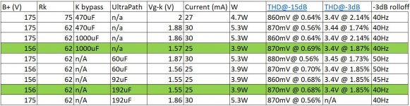
I'm attaching the table of results, if I am calc Pdiss correctly, then the lowest I measured was 3.9W which is 86% of max .... too much?
What looks best to you, or would you try and other values?
I ran a bunch of tests now --
- B+ 175V vs 155V
- Cathode bypass vs UltraPath
- Cathode cap 470uF vs 1000uf
- UltraPath cap 60uF, 90uF, 190uF
- Rk 75ohms vs 62ohms
Preliminary results:
-62R measured better than 75R
-Cathode bypass had better low frequency response than UP, small/no difference between 470uF and 1000uF. UltraPath low frequency response was improved with increased capacitance, almost as good as the Cathode bypass.
-175V measured better than 155V but not significantly and may not be worth the extra dissipation
-I'm not sure of the significance but the roll-off of UltraPath measures much "smoother"
I'm re-considering my original plan to buy a pair of Lundahl 2766/30mA which have a primary inductance of 43H.
I've used this CXSE 5W in an EL84 SE amp before and there was no issue with low frequency roll off, likely due to the much higher Rp.
Few theoretical questions:
- To calculate Plate dissipation, is it this formula correct? -- Vp * (Vg-k/Rk)
- I don't understand how the grid voltage is set. It changes based on Rk and Vp but does anything else determine it?
I'm attaching the table of results, if I am calc Pdiss correctly, then the lowest I measured was 3.9W which is 86% of max .... too much?
What looks best to you, or would you try and other values?
Attachments

The plate resistance (rp) of the triode and the primary inductance (Lpri) of the output transformer will dictate the open loop low frequency response of the amplifier into its load.


(fc is the same thing as what I've been writing as F3)
If rp = 2k and Lpri = 4H then
2000/6.283*4 = 79.58 Hz
fc = about 80 Hz
Can you try measuring the OPT's primary inductance with a 50 ohm load (many headphones) and a 300 ohm load (Sennheiser HD600, etc.)?
You can increase bandwidth by applying negative feedback to the amplifier, but the open loop frequency response will be set by rp in series with Lpri.
When you used this transformer with an EL84, did you triode-wire the EL84, or did you use the OPT's 'ultralinear' tap?
Did that EL84 circuit have NFB around it?
To calculate plate dissipation (Pdiss) simply multiply the tube's plate-to-cathode DC voltage (Vp) by its plate current (Ip).
With a cathode biased common cathode triode stage (like your 5842) you can find Ip by dividing the voltage at the tube's cathode (Vk) by the value of the cathode resistor (Rk).
For Vg = 1.57V and Rk = 62R,
1.88/62 = 25.3 mA
If Vp = 156V and Ip = 25.3mA,
156V * 0.0253A = 3.95 W
That's within the 5842 max plate dissipation spec of 4.5W.

If you want to make a SET headphone amp with zero NFB and that OPT, and you want that amp to reach down to 50Hz, then I think you'll need a triode with mu of >30 and rp of closer to 1k ohms.
12GN7A-triode is close to that, which is why I'm using it in my amp. According to Pete Millet's measurements, its rp should be around 1100 ohms, and mu somewhere in the 35 to 40 range. http://www.pmillett.com/pentodes.htm
FWIW, I tried an ultrapath connection of the cathode bypass capacitor and didn't notice any improvements.
I also tried paralleled green LEDs and I actually prefer the sound of the standard Rk//Ck. Perhaps I have poor taste. I don't know...
Is this the OPT you're using?
https://edcorusa.com/collections/tu...-125a35a-022905-125a3a?variant=41131379654843
It looks like its maximum standing current on the primary is 40mA. Perhaps it's getting too close to saturation with 30mA plate current applied?
I wonder what would happen if you used a pair of 6N6P triodes in parallel, with each triode set to draw 15mA plate current (total of 30mA per side). The combined rp of the two 6N6P in parallel would likely be down around 1k ohms, or maybe a little lower. That might help your bass response. However, the gain will be lower, about 20x at the most. That means your amplifier would end up at around unity gain with the 17.5:1 stepdown ratio of the transformer.
It does look like if you want to use 5842 for a simple SET w/ no NFB, you'll need an OPT with higher primary inductance.
--
(fc is the same thing as what I've been writing as F3)
If rp = 2k and Lpri = 4H then
2000/6.283*4 = 79.58 Hz
fc = about 80 Hz
Can you try measuring the OPT's primary inductance with a 50 ohm load (many headphones) and a 300 ohm load (Sennheiser HD600, etc.)?
You can increase bandwidth by applying negative feedback to the amplifier, but the open loop frequency response will be set by rp in series with Lpri.
When you used this transformer with an EL84, did you triode-wire the EL84, or did you use the OPT's 'ultralinear' tap?
Did that EL84 circuit have NFB around it?
To calculate plate dissipation (Pdiss) simply multiply the tube's plate-to-cathode DC voltage (Vp) by its plate current (Ip).
With a cathode biased common cathode triode stage (like your 5842) you can find Ip by dividing the voltage at the tube's cathode (Vk) by the value of the cathode resistor (Rk).
For Vg = 1.57V and Rk = 62R,
1.88/62 = 25.3 mA
If Vp = 156V and Ip = 25.3mA,
156V * 0.0253A = 3.95 W
That's within the 5842 max plate dissipation spec of 4.5W.
If you want to make a SET headphone amp with zero NFB and that OPT, and you want that amp to reach down to 50Hz, then I think you'll need a triode with mu of >30 and rp of closer to 1k ohms.
12GN7A-triode is close to that, which is why I'm using it in my amp. According to Pete Millet's measurements, its rp should be around 1100 ohms, and mu somewhere in the 35 to 40 range. http://www.pmillett.com/pentodes.htm
FWIW, I tried an ultrapath connection of the cathode bypass capacitor and didn't notice any improvements.
I also tried paralleled green LEDs and I actually prefer the sound of the standard Rk//Ck. Perhaps I have poor taste. I don't know...
Is this the OPT you're using?
https://edcorusa.com/collections/tu...-125a35a-022905-125a3a?variant=41131379654843
It looks like its maximum standing current on the primary is 40mA. Perhaps it's getting too close to saturation with 30mA plate current applied?
I wonder what would happen if you used a pair of 6N6P triodes in parallel, with each triode set to draw 15mA plate current (total of 30mA per side). The combined rp of the two 6N6P in parallel would likely be down around 1k ohms, or maybe a little lower. That might help your bass response. However, the gain will be lower, about 20x at the most. That means your amplifier would end up at around unity gain with the 17.5:1 stepdown ratio of the transformer.
It does look like if you want to use 5842 for a simple SET w/ no NFB, you'll need an OPT with higher primary inductance.
--
Last edited:
Thanks for all the details, let me go over it again to understand it properly.
My choice for 5842 is simply because I have 3 nice pairs, Raytheon with Windmill getters, Amperex gold pin and Ericsson 417A.
My choice for 5842 is simply because I have 3 nice pairs, Raytheon with Windmill getters, Amperex gold pin and Ericsson 417A.
I measured with 33, 100 and 300ohm (resistors I had).... it was approx. 7.5H, 9.5H, 10.5H.Can you try measuring the OPT's primary inductance with a 50 ohm load (many headphones) and a 300 ohm load (Sennheiser HD600, etc.)?
This was with the RH84, pentode-wired with Schade/plate to plate feedback (no UL).When you used this transformer with an EL84, did you triode-wire the EL84, or did you use the OPT's 'ultralinear' tap?
Did that EL84 circuit have NFB around it?
Yes those were the ones. The RH84 was actually biased to around 45mA with a CCS and there was no problem with LF response if I remember correctly. Maybe because the output is much lower than the rated 5W of the OPT.Is this the OPT you're using?
It looks like its maximum standing current on the primary is 40mA. Perhaps it's getting too close to saturation with 30mA plate current applied?
I actually have another assembled PCB for the RH84 so I'll hook it up in the same test setup I have an re-measure with this OPT.
Yea, I am probably abandoning the UltraPath idea. It seems like there needs to be atleast 200uF at the Cathode for proper LF and those values are much easier to get in the 10V ratings than 250V ratings. Also, there was no measurable difference to THD and my final PSU will not be as quiet as the Maida so all of those things considered Rk//Ck for me as well.FWIW, I tried an ultrapath connection of the cathode bypass capacitor and didn't notice any improvements.
I also tried paralleled green LEDs and I actually prefer the sound of the standard Rk//Ck. Perhaps I have poor taste. I don't know...
The LL2766 will probably be perfect for this application but rethinking this, I can't justify the cost for the final power of this amp. For example, the LL1663 is similarly priced and I used those for a TSE 300B which sounded amazing.It does look like if you want to use 5842 for a simple SET w/ no NFB, you'll need an OPT with higher primary inductance.
You can increase bandwidth by applying negative feedback to the amplifier, but the open loop frequency response will be set by rp in series with Lpri.
I have a pair of GXSE10 arriving for a different project, I assume they have higher inductance than the smaller CXSE. I'll hook them up when they arrive to see the differences in LF.
I'm open to trying NFB... the headphones I have are HD660s (150ohm), HD650 (300ohm) and DT1990 (250ohm), so don't really need that much power.
How does the schematic need to change for that?
I think the reason you didn't notice a lack of bass response from the RH84 version was because that has negative feedback from the plate of the EL84 to its grid, via the plate of the 12AT7 (shunt feedback). The negative feedback compares the frequency response coming from the plate of the EL84 to the input at its grid, sees that there's less bass at the plate than at the grid, and boosts the bass back up.I'm open to trying NFB...
With a 12AT7 supplying about 25x gain and the EL84 supplying at least 20x gain, there's lots of gain available to lose by applying negative feedback, even with the voltage stepdown of the OPT.
However, with a single 5842, there's only about 25x gain. Then you have an OPT with a stepdown ratio of about 17.5:1. You don't have much gain to lose by applying NFB.
It's a problem with this design. One tube can't provide enough gain to lose by applying NFBn along with sufficiently low rp to not introduce too much of a roll-off in the bass. You need a two-stage amplifier circuit to make enough gain open loop to drive the NFB loop (closed loop).
You have some nice examples of 5842. Do you listen to vinyl records at all?
@rongon thanks again for your support and explanations throughout this thread.
If NFB is out, before I abandon this project is it worth considering a Parafeed design? I might be able to find a more suitable and smaller OPT.
Also, that would end up fairly similar to the Bottlehead Mainline I believe, no?
If I end up abandoning the 5842 HP amp, other tubes I have quite a bit of are 6922's, so this could be an option: https://diyaudioprojects.com/Tubes/6DJ8-Tube-Headphone-Amp/
If NFB is out, before I abandon this project is it worth considering a Parafeed design? I might be able to find a more suitable and smaller OPT.
Also, that would end up fairly similar to the Bottlehead Mainline I believe, no?
Yes, and I see you replied in my other thread as well. Basically I am trying to find the right project around these 5842's.... I've built Tubelab SE in the past and I dont really have a need for one anymore. Phono stage is the other option, but I've got quite a few as it is.... hence this thread.You have some nice examples of 5842. Do you listen to vinyl records at all?
If I end up abandoning the 5842 HP amp, other tubes I have quite a bit of are 6922's, so this could be an option: https://diyaudioprojects.com/Tubes/6DJ8-Tube-Headphone-Amp/
5842 and 6922 are both excellent for phono preamps.
In Merlin Blencowe's book "Designing High Fidelity Tube Preamps", the author provides an example of a White Cathode Follower using 6DJ8s that would be suitable for high impedance headphones like Sennheiser HD-600, etc. Perhaps that would be worth exploring?
I built a kind of brute-force-and-ignorance headphone amp using multiple 6DJ8s, because I have a lot of them too. It uses four 6DJ8s. Each channel is a single 6DJ8 triode common cathode amp DC coupled to three 6DJ8 triodes in parallel as a cathode follower, with some NFB from the output to the grid of the first stage 6DJ8 (basically "Schade" feedback). I gave it to my brother. He uses it with a pair of Sennheiser HD-580 cans.
However, neither the White Cathode Follower nor the Brute-Force-and-Ignorance Cathode Follower use an output transformer. They both require a large value output capacitor. That gives some people the willies.
Thanks for the tip, so it sounds like for the 5842 headphone amp as I have it now, either I can accept -3dB at 45-50Hz (as measured) with the current OPT or try a different OPT.
With a better OPT (better == more inductance) I probably don't need NFB but what if I went with a lower turns ratio OPT, like 5:1 or 10:1, something like https://www.sowter.co.uk/specs/1160.html
These are just as pricey with the Lundahl but if I get good bass and 3X more power (in the 5:1 configuration) it might be worth it
However, with a single 5842, there's only about 25x gain. Then you have an OPT with a stepdown ratio of about 17.5:1. You don't have much gain to lose by applying NFB.
With a better OPT (better == more inductance) I probably don't need NFB but what if I went with a lower turns ratio OPT, like 5:1 or 10:1, something like https://www.sowter.co.uk/specs/1160.html
These are just as pricey with the Lundahl but if I get good bass and 3X more power (in the 5:1 configuration) it might be worth it
Hmmm.... I don't know.
When it comes to bass response, the primary inductance is the critical specification, not so much the turns ratio.
It says the primary inductance is 40H. That is enough for the 5842.
The specs say the max current to the primary is 20mA. If you go beyond that the primary inductance will fall quickly.
Is this transformer suitable for use as a headphone amp OPT?
I'm not sure why not ?
Max DC current is 30mA, the preferred operating point based on my testing would be around 25mA with Rk=60ohms and Vp=150.
There could be an issue if bandwidth is not as good outside the nominal impedance of 15k:600 (10:1) or 15k:150 (5:1).
I tested earlier with around 1.4V input there was 36VAC at the plate and 2VAC at the output to 300ohms (makes sense with the existing 17.5:1 OPT), roughly 13mW.
If noise is good with 5:1, the same input would provide 173mW, seems significant no?
Very interesting thread.
Is there any reason you really would like to use a transformer? It does hugely increase cost,
and if you use a twin triode (5842, 12AU7, 6DJ8, 6SN7) you can use the first section in plate load, and
the second triode directly connected with output taken at the cathode as a CF.
This will limit your Zout to about 100R, but if you want it lower, you can use a small mosfet in source follower for Zout around 1-5R.
Transformer from plate will give you lowish Zout, with 12.5:1 turns ratio about 156 less than plate resistor paralelled with rp, but little less than 40R. But more cost........
Hugh
15k:150 would have a 10:1 stepdown ratio.
With 0.5V input to a 5842 (35x gain), that would make about 12.5V at the plate.
17.5/10 = 1.75V (that's plenty!).
The DC resistance of the transformer primary is 640 ohms. The DC resistance of the secondary is 50 ohms. That will introduce some insertion loss.
I'll guess that the output voltage secondary to 300 ohm load will be roughly 1.5V. That's a total gain of about 3x, which is probably enough with most cans.
As long as the primary inductance stays up near 40H with 25mA standing current across its primary, my guess is that this Sowter line transformer should work nicely. It does look like a high quality transformer.
Incidentally, the transformer I used was Edcor XSE10-8K-50. That is a 12.65:1 stepdown. The tube I use has a lower mu too -- gain is probably down near 25x. I find that the combination works well with Sennheiser HD650 cans. With less sensitive Fostex T50RP cans the low gain becomes an issue, but they still get loud enough for me. I just have to crank the volume control up around 2 o'clock or so.
An issue I completely forgot about is the triode's input capacitance. The 5842 has appreciable input C due to Miller effect. It's Cgp is probably about 1pF + 0.7pF for strays, so expect the input C to be up around 100pF. If you're using a 100k volume control, its maximum output impedance is going to be 25k ohms. An RC of 25k and 100pF = F3 of 63.6kHz.
I like to see less of a high frequency roll-off from the volume control, so I'm using a 25k stepped attenuator in the headphone amp. The 12GN7A-triode has input C of about 100pF and gain of roughly 25. The max output resistance of a 25k pot is about 6.25k ohms, which means the F3 at high frequency will be about 250kHz, which is high enough to not matter. I originally had a 100k pot in the amp, but I could hear a definite improvement in the high frequencies when I replaced that with the 25k pot -- even with my tired old ears.
Last edited:
Hi HughVery interesting thread.
Is there any reason you really would like to use a transformer? It does hugely increase cost,
and if you use a twin triode (5842, 12AU7, 6DJ8, 6SN7) you can use the first section in plate load, and
the second triode directly connected with output taken at the cathode as a CF.
This will limit your Zout to about 100R, but if you want it lower, you can use a small mosfet in source follower for Zout around 1-5R.
Transformer from plate will give you lowish Zout, with 12.5:1 turns ratio about 156 less than plate resistor paralelled with rp, but little less than 40R. But more cost........
Hugh
5842 is a single triode. It's equivalent to a Western Electric 417A.
A MOSFET source follower could be used to good effect, yes.
The gain would be excessive (roughly 35x) but that would just beg for NFB, which would lower Zout even more. The MOSFET would be more capable of driving the combined (heavy) load of the headphones and the NFB loop.
In simulation I found that in order to achieve low distortion into a 50 ohm load, the tube needs a high enough B+ to work well (at least 150V for a 6DJ8) and the MOSFET has to draw enough current to sink sufficient current into the load. (With a B+ of 150V I figure the MOSFET will dissipate 4W.) The result is that a decently big heatsink is required, along with six 3-watt rated power resistors or a pair of 1.3k 10W wirewound resistors. I also would use a 200uF film cap for C2 (I have some surplus motor run caps to use there). All that's still not as expensive as a really good pair of output transformers, though.
This is a circuit I was working on a while ago. I never built it, so it's just a thought experiment at this point.
It does load down into a 32 ohm load. While the THD is a super-low 0.02% at 1V out into a 300 ohm load, it worsens to 0.08% with 10mW into a 32 ohm load. However, that's probably hi-fi enough for a tube amp with low impedance cans since 10mW will probably make you deaf with those on.
Last edited:

Hi Hugh
5842 is a single triode. It's equivalent to a Western Electric 417A.
A MOSFET source follower could be used to good effect, yes.
The gain would be excessive (roughly 35x) but that would just beg for NFB, which would lower Zout even more. The MOSFET would be more capable of driving the combined (heavy) load of the headphones and the NFB loop.
In simulation I found that in order to achieve low distortion into a 50 ohm load, the tube needs a high enough B+ to work well (at least 150V for a 6DJ8) and the MOSFET has to draw enough current to sink sufficient current into the load. (With a B+ of 150V I figure the MOSFET will dissipate 4W.) The result is that a decently big heatsink is required, along with six 3-watt rated power resistors or a pair of 1.3k 10W wirewound resistors. I also would use a 200uF film cap for C2 (I have some surplus motor run caps to use there). All that's still not as expensive as a really good pair of output transformers, though.
This is a circuit I was working on a while ago. I never built it, so it's just a thought experiment at this point.
View attachment 1123882
It does load down into a 32 ohm load. While the THD is a super-low 0.02% at 1V out into a 300 ohm load, it worsens to 0.08% with 10mW into a 32 ohm load. However, that's probably hi-fi enough for a tube amp with low impedance cans since 10mW will probably make you deaf with those on.
I really like this design and how it runs from a single supply. Don't need any more projects at the moment but there's a Digikey shopping cart calling my name...
I know what you mean! So many projects (and so many parts lying around), yet so little time...
That last circuit is basically the same as the one I built for my brother, except instead of three 6DJ8 triodes in parallel for the cathode follower output, a simpler and much cheaper MOSFET source follower is used.
Either way, NFB is what puts these designs over the top. I originally built my brother's headphone amp with no NFB. I tried listening to it for a while, and at average listening levels I have to say, I'd prefer to listen through my old Objective2 over that kind of thing. But after reconfiguring the circuit to apply 10dB or so of NFB, I ended up enjoying the sound a lot more. It's warmer and more 'tubey' sounding than my 12GN7A-triode OPT-coupled headphone amp, even with the NFB applied. But they both sound subjectively clean.
I think using a White Cathode Follower as the output stage in the above would perform even better. I think it was Artosalo who shared a design that models so spectacularly well I couldn't believe it. I'll see if I can find its schematic when I'm home. It's an interesting design.
- Home
- Amplifiers
- Tubes / Valves
- 5842 headphone amplifier