Have you tried actually listening to it yet with the intended headphones?
Sounds like it's working fine to me, don't agonise over the gain issue unless it does not go loud enough for you.
my 2 cents, ymmv, etc
Sounds like it's working fine to me, don't agonise over the gain issue unless it does not go loud enough for you.
my 2 cents, ymmv, etc
There is one unexpected result (to me), and would appreciate some help understanding.
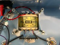
The OPT is configured in the 12:1 ratio, terminated with a 32R resistor, which resulted in mu=30.
Changed the 32R resistor to 100R, mu is closer to 40.
This behavior is what I observed when increasing the load from 5K in the previous SE setup.
This was unexpected, because I was under the impression that the CCS always provides a high impedance to the plate, regardless of whether the secondary is connected to 32 or 300 ohms.... Is this not correct or perhaps I made a mistake in wiring?
In a triode driving a transformer in parafeed arrangement, the load on the triode plate is both the CCS (or choke) and the transformer primary, with the coupling capacitor too.
Since the transformer primary is part of the load, changing the load on the transformer secondary will also change the impedance reflected back to the primary.
If your transformer has a nominal impedance of 5k ohms primary : 50 ohms secondary, and you put a 50 ohm load on the secondary (i.e., your headphone's impedance is 50 ohms) then the primary appears as a 5k ohm load to the triode.
However, if you increase the value of the headphone/secondary load to 300 ohms, you've increased that by 6x. The load reflected through the primary will also increase by 6x, to 30k ohms!
To a 6S45P with rp (Zout) of approximately 2k ohms. a 5k ohm primary load will be a fairly heavy one. This will reduce the gain available from the triode to significantly less than the mu of the triode.
However, if the primary load appears to be 30k ohms, this will be a very light load, and the triode will be able to deliver gain much closer to its mu (the voltage gain of the triode will go up).
This sounds to me like what you described happening when you changed the secondary load on your transformer.
The CCS part of the load on the triode does stay very high at all times, but it is in parallel with the load presented by the transformer primary. Since the value of the transformer primary load (in ohms) is a much lower value, that is the characteristic that will dominate.

@rongon, I use the 6S45P/6C45P quite a bit, indeed I used them in Mr Potatohead referred to earlier in this thread.
My recollection is that the tube's Rp is closer to 1200ohms, maybe even a bit less. It is basically the ruskie vesion of the 437 iirc.
Other than that I agree with everything in your post. 🙂
The Altec 15095 strapped 15k:150 used i Mr Potatohead is a 10:1 step ratio, and it drives my HD600 (300 ohm) and HD25 (70 ohm) with no problem in the bass are at all. A 30 ohm load might be a bit borderline though with output from the plate to the primary of the parafeed OPT.
The OPs Sowter 8665 (which should sound very good being 50% Ni, imho) strapped to 12:1 should reflect about 5k ohms with a 30 ohm load which should be just fine for the 6C45P/6S45P if the output is taken from the tube plate..
Mr Potatohead is similar in execution to Doc B's Kugelis, see below, except I used a cascode depletion mosfet CCS and a 1.7V LED in the cathode and a lower B+ (150V) and 20mA through the tube. I didn't write the curcuit down, but I "might" have taken the Mu output of the cascode CCS instead of from the plate. I think I used a standard 50k ohm audio taper pot for volume control and used a 100ohm plate stopper rather than the 50 ohm indicated in the Kugelis circuit.
It sounds great!
Attachments

Thanks for the explanation @rongon, that makes sense.
@DrowningNotWaving that is a great looking amp, congrats. Thanks for the details, I'm pretty much aligned with all that..... from my testing between the 5842 and 6C45 I'm leaning towards the 6C45. That Doc. B amp is pretty close to the current Mainline they sell.
I will test the D3a tomorrow and make a final decision.
BTW, from my testing, 30mA performed better than 20mA and 17mA (as used in the Mainline)
And, I haven't listened to it yet, ... soon!
@yan24 it isn't my drawing, sorry. 🙂 It is from the now defunct Valve webzine. My understanding is that the CCS shown is a representation of the Bottlehead C4S circuit, which I believe is sold commercially, so it could be a deliberate misrepresentation or more likely an unintended error.
I did have a pair of C4S kits for an old, old project 20 years ago but they were a little finiky to set up by comparison with the depletion mosfets I use at the moment ( depletion mosfet CCS are simple and easy to execute).
I did have a pair of C4S kits for an old, old project 20 years ago but they were a little finiky to set up by comparison with the depletion mosfets I use at the moment ( depletion mosfet CCS are simple and easy to execute).
The project is still alive.... I ended up with mostly the Papa Rusa with some modified construction details.
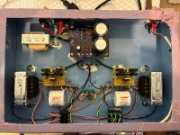
The build will be mostly P2P with the CCS and PSU on PCB's.
PSU is SS bridge rectifier (1k+1nF snubber) and CLC 220uF-5H-220uF.
The CCS is the cascode DN2540N5 as described in SY's HMN and ImPasse projects.
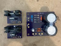
The CCS PCB will be mounted directly on top of the tube socket (as shown below)
I will be using 6C45Π at 25mA, with a fixed 56R cathode resistor for -1.4 grid voltage. (Although same build can be used with a 5842/D3a)
No plans to use a cathode bypass cap, unless that results in increased noise (I've read a few threads where adding the cathode bypass cap eliminated some hum/buzz).
AC heaters elevated to ~50V DC with 10nF ceramic caps from the heater pins to chassis.
I also realized I have enough parts to build more than one, so first a prototype with the Hammond 269GX PT and Hammond 119DA output transformers and the final build will be with a nice ISO(i.e former Tango) PT and the Sowter 8665A.

The build will be mostly P2P with the CCS and PSU on PCB's.
PSU is SS bridge rectifier (1k+1nF snubber) and CLC 220uF-5H-220uF.
The CCS is the cascode DN2540N5 as described in SY's HMN and ImPasse projects.
The CCS PCB will be mounted directly on top of the tube socket (as shown below)
I will be using 6C45Π at 25mA, with a fixed 56R cathode resistor for -1.4 grid voltage. (Although same build can be used with a 5842/D3a)
No plans to use a cathode bypass cap, unless that results in increased noise (I've read a few threads where adding the cathode bypass cap eliminated some hum/buzz).
AC heaters elevated to ~50V DC with 10nF ceramic caps from the heater pins to chassis.
I also realized I have enough parts to build more than one, so first a prototype with the Hammond 269GX PT and Hammond 119DA output transformers and the final build will be with a nice ISO(i.e former Tango) PT and the Sowter 8665A.
Attachments
I also realized I have enough parts to build more than one, so first a prototype with the Hammond 269GX PT and Hammond 119DA output transformers and the final build will be with a nice ISO(i.e former Tango) PT and the Sowter 8665A.
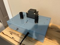
Almost finished with the "prototype" build ... the amp is silent (no hum or buzz) and sounds VERY good. Unfortunately, it seems like one of the 119DA was faulty since I was getting no output from the 8ohm terminal, so I need to replace it.
Total power is impressive, over 500mW to 100ohm headphones and easily 150mW+ to 300ohms.
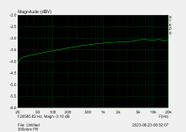
FR from 20Hz-20kHz is within 1dB, but definitely not as flat as the tests with the Sowter OPT's. Although, a pair of 119DA costs half of a single Sowter so definitely a cost-effective solution.
I will post pictures of the external builds once finalized.
Attachments
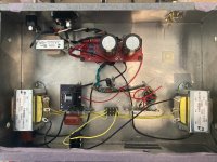
I finished the second build, this time with D3A in triode mode and Sowter 8665 transformers.
B+ ~250V (CLC power supply, 220uF - 10H - 220uF)
Ip 20mA (CCS)
Vg -1.41V (70.5ohm resistor)
Vp ~140V
I initially used an IR LED with ~1.37V forward voltage but the frequency response and output power were not as good as with the un-bypassed resistor.
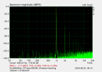
Overall lots of power (less than 6C45P though), good frequency response. No hum or buzz. Sounds very good.
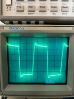
Attached is scope view of 10kHz square wave, 100ohm secondary, once with 12:1 and then 6:1.
With frequency response scopes, there is visible HF roll-off in 12:1.
What can I learn about these? Is there any oscillation that needs to be addressed?
B+ ~250V (CLC power supply, 220uF - 10H - 220uF)
Ip 20mA (CCS)
Vg -1.41V (70.5ohm resistor)
Vp ~140V
I initially used an IR LED with ~1.37V forward voltage but the frequency response and output power were not as good as with the un-bypassed resistor.
Overall lots of power (less than 6C45P though), good frequency response. No hum or buzz. Sounds very good.
Attached is scope view of 10kHz square wave, 100ohm secondary, once with 12:1 and then 6:1.
With frequency response scopes, there is visible HF roll-off in 12:1.
What can I learn about these? Is there any oscillation that needs to be addressed?
Attachments

- Home
- Amplifiers
- Tubes / Valves
- 5842 headphone amplifier