In my testing when I took one of my 5 amplifiers and put a resistive 8 ohm load on it and drove it to clipping (checking the wave with oscilloscope) the powersupply voltage dropped only about 2V from the normal 35V.
IF you check these tests:
DIY BPA300 6x LM3886 300W audio Amplifier
At full load (which is 300W with 6 lm3886's) his voltage only dropped from 34.5V to 31V.
And he uses the exact same toroidal as I am using. Except that his is encapsulated.
IF you check these tests:
DIY BPA300 6x LM3886 300W audio Amplifier
At full load (which is 300W with 6 lm3886's) his voltage only dropped from 34.5V to 31V.
And he uses the exact same toroidal as I am using. Except that his is encapsulated.
DIY AUDIO TÜRK?YE • Ba?l?k görüntüleniyor - 5 Kanal LM3886 uygulamas?
This and
DIY AUDIO TÜRK?YE • Ba?l?k görüntüleniyor - JBL GT5-12 ile aktif subwoofer projesi..
This projects may usefull for you..
The second one is a "turbo boosted" subwoofer project and will work any 12" subwoofer in a ~30lt sealed box...
All designed and tested by me.
This and
DIY AUDIO TÜRK?YE • Ba?l?k görüntüleniyor - JBL GT5-12 ile aktif subwoofer projesi..
This projects may usefull for you..
The second one is a "turbo boosted" subwoofer project and will work any 12" subwoofer in a ~30lt sealed box...
All designed and tested by me.
Last edited:
read the datasheet.
It explains why heatsink and chip temperatures are dependent on ambient temperature, load impedance, supply voltage and output power, both average and peak.
It then goes on to show how to design for all of these variables and choose heatsink to match supply voltage
It explains why heatsink and chip temperatures are dependent on ambient temperature, load impedance, supply voltage and output power, both average and peak.
It then goes on to show how to design for all of these variables and choose heatsink to match supply voltage
Will 35 volt rails cause the chip to get too hot?
Nothing causes the chip to get too hot other then current. the lm3886 will handle a 80v swing i believe so 70v should be no problem. Just stick with 25vac transformers and under and yull be fine.
Absolutely right. In a 5.1 system it is very rare that all channels get peaks at the same time. In that case with a single transformer for all channels you can use a smaller VA rating than with one transformer per channel, e. g. 500 VA instead of 750 VA. 5.1 means you have a subwoofer. In that case the 5 channels should be high-pass filtered which relieves them of the bass where most of the energy goes. You could probably even do with a much smaller transformer then. Depends on the speakers, though.
Using one power supply per channel makes sense when you put each amplifier right next to the corresponding speaker.
Using one power supply per channel makes sense when you put each amplifier right next to the corresponding speaker.
Ok. I think I will be using two transformers to avoid too high of a VA rating. I think they will both be 25-0-0-25 300VA from Antek (Antek - AN-3225). This should give me 25 x 1.41 - (2 x 0.7) = 33.85V rails. For an output power of 50W and a load of 8 ohms, I get Vopeak = sqrt (2x50x8) = 28.3 V at Iopeak = sqrt ((2x50)/8) = 3.5A. To the 28.3V I should add the dropout voltage according to the datasheet, but I cannot figure out what that voltage is. However, at the beginning of the datasheet it says that the LM3886 gets 50W average power into 8 ohms with 35 volt rails. So, are these numbers okay? Will my transformer work? Do I need to figure in the transformer and mains regulation?
Your gonna be fine. At this point your splitting hairs, and your doing absolute peak sustained output. The chip can handle the little extra for short bursts and your nowhere near the voltage limits nor th do you have a low impedance load. Your transformer is not going to be perfect, its going to droop a good volt or 2 durring loads, and your mains will vary between 110-130vac if your in the usa.
As for the transformer, id shoot for just one AN-5225
As like 3 other people have stated, 500va is VERY good considering your never going to be pushing more then 100watts out at any given time. the 500va is is even over kill considering you can get away with a 100 watt lm3886 with 200va unit.
I still stand by my recommendation of 1 large transformer rather then multi small ones, to help with regulation. I would also make just one huge power supply to feed all of them. It is the simplest and easiest to trouble shoot. it also means that like the shared transformer, each of the amps gets all the juice they could ever ask for with a 500va rated power supply.
For diodes you can get beefy and use the fairchild 15amp steath versions and make just one power supply
http://www.fairchildsemi.com/ds/FF/FFPF15S60S.pdf
Ok. I think I will be using two transformers to avoid too high of a VA rating.
What's the point of that. You still need the same total VA rating. About the only reason to go with two is either (1) the large transformers is to tall to fit inside yur chassis or (2) you want to use a lower powerd amp for the rear channels and you can save some money by using two. (3) Like #2 but one transformers feeds a subwoofer amp. (4) you already have the amps and want to used them Maye there is a #5 I can't thinks of
Now had you said you wanted to use five transformers to feed five mono amps, that would be different.
5 channels:
500VA 25 0 25 transformer for 5 channels.(giving 35 0 35V)
at least 100uF per voltage rail at each lm3886 cheap (10 total)
At the very least 20000uF per voltage rail just after bridge diodes.
Subwoofer (.1 channel)
Keep this a separate project. Separate power supply , separate everything.
You will first have to decide if you want to use more chip amps or go solid state or most efficient Class-D.
I agree.5 channels:
500VA 25 0 25 transformer for 5 channels.(giving 35 0 35V)
At the very least 20000uF per voltage rail just after bridge diodes.
5channels @ ~60W into 8ohms. The PSU sees a load of 8/5 ohms.
I would estimate you will hear changes by increasing the +-20mF to +-60mF if your 5channels are all wideband.
If you filter all 5 channels so that low bass is not fed to them then you can reduce the smoothing capacitance, but you must also reduce the high pass filter frequency at the input of each of the 5channels and make the complementary reduction in the NFB DC blocker as well.
I think I will go with one 500 VA 25-0-0-25 transformer. Should I make two bridge rectifiers (one for each rail) or just one? For the capacitors, if I need 10,000uF, can you recommend a type that is available from Digi-key? Panasonic FM and FC do not reach 10,000 uF at 50v.
Can you explain this a little more? I am new at this. If I am using a Dolby 5.1 decoder, won't it filter out the bass automatically for the LFE channel?
Also, can you tell me where you get your heat sinks? From my calculations, I need one with a thermal resistance no higher than 2.6. I calculated the peak power dissipation to be 31W and the average power dissipation to be 28.8W. The best one I can find on Digi-key has a thermal resistance of 2.6. This seems to be cutting it close, but maybe it is okay because the amp won't always run at full output?
If you filter all 5 channels so that low bass is not fed to them then you can reduce the smoothing capacitance, but you must also reduce the high pass filter frequency at the input of each of the 5channels and make the complementary reduction in the NFB DC blocker as well.
Can you explain this a little more? I am new at this. If I am using a Dolby 5.1 decoder, won't it filter out the bass automatically for the LFE channel?
Also, can you tell me where you get your heat sinks? From my calculations, I need one with a thermal resistance no higher than 2.6. I calculated the peak power dissipation to be 31W and the average power dissipation to be 28.8W. The best one I can find on Digi-key has a thermal resistance of 2.6. This seems to be cutting it close, but maybe it is okay because the amp won't always run at full output?
Id just clone chipamps.com power supply and just beef up the diodes.
Yes you need 2 bridges, one fore B+ and one for B-
If your set on fc/fm (they are nice arnt they) just use 2-3 instead of 1 big one, this helps even more because it lowers the esr.
Andrew is harping on the fact that higher notes dont need as big of a capacitor bank, so if you wanted to just use fc/fm, you could get away with 5,000uf. Infact it might work out well since your caps will have a lower esr then stock. The could be an option only if your setting all your speakers to small in your dolby digital menu of your preamp. If your running your fronts full range then dont reduce your cap bank, and dont adjust your input dc blocker caps.
Andrews other idea isnt a good one in my opinion. Hes talking about adjusting the amps input capacitor to filter out the 80hz and below and turning the input cap and the NFB DC blocker into a working high pass filter, instead of its intended purpose as just a dc input blocker. This will cause phase issues and should be avoided.
AS for heatsinks, id use a case with them built in. if not you might beable to use something like a make each side of the case a 1/4-1/2" thick piece of aluminum with a set of amps on each side. Another idea i did was use cheap computer heatsinks. P4 heatsinks are dirt cheap and have copper centers half the time.
I think I will go with one 500 VA 25-0-0-25 transformer. Should I make two bridge rectifiers (one for each rail) or just one?
With one rectifier, the rectifier needs to be rated for twice the current as compared to if you used two. So just look if the diodes you want to use come in the required ratings. Maybe you want to use "fast" diodes and they don't come in 20A? So it comes down to practical conciderations
Again this is my personal setup ,and not law:
if you are using a surround decoder you won't need to filter for sub or high pass signal to 5 channels.
Just make sure of the settings on your decoder. MY personal setting is 5.1 when a movie is played (that has surround sound) so that the Sub-woofer handles everything below 80hz
And 2.0 when music is played.
In party mode when I want to be loud I set my decoder to have the .1 channel switched on when playing music so that it handles the below 80hz frequencies and the two front speakers only handle 80hz + frequencies.
I used the standard non inverting schematic:
http://diyaudioprojects.com/Chip/LM3886_CA/F01-LM3886-chipamp.png
5 changes I made to this schematic:
1) I changed R3 to 1.5k ohm since i didn't need/want the high gain which was too sensitive on my decoder volume control. I could not even reach the -10DB setting for Massive neighbor bothering volumes. Use the overture xls file and the output voltage spec from your decoder to decide gain. Gain must not be lower than 20db
2) I took out Rin. Use individual volume settings on your decoder if you want to change volume on some channels for different room placements or speaker sensitivity.
3) I removed R1 and replaced with 2.2uF capacitor which gives me -3db at 3hz which is slightly low so you could easily change that to 1 uF
4) I added 2.2K resistor between R2 and pin 10(+ input) of the lm3886
5) 220pF cap between + - inputs of lm3886 to help get rid of high frequency noise
I would suggest using 40000uF on each voltage rail. This should be AMPLE for 5 channel above 80hz source and be MUCH more than enough for when you do stereo full range or stereo above 80hz.
Last edited:
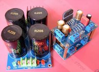
For the power supply i wanted to keep the build easy and trouble free.
I Used two of these rectifiers:
http://www.wind-turbine-supplies.co.uk/images/Square_Bridge_Rectifier.jpg
35A 400V. DIRT cheap. Works perfectly. Very strong. No PCB tracks , wires from Toroidal secondary soldered DIRECTLY onto them. Bolting them onto metal surface of enclosure.
I Used two of these rectifiers:
http://www.wind-turbine-supplies.co.uk/images/Square_Bridge_Rectifier.jpg
35A 400V. DIRT cheap. Works perfectly. Very strong. No PCB tracks , wires from Toroidal secondary soldered DIRECTLY onto them. Bolting them onto metal surface of enclosure.
no, he is not.Andrews other idea isn't a good one in my opinion. He's talking about adjusting the amps input capacitor to filter out the 80hz and below and turning the input cap and the NFB DC blocker into a working high pass filter, instead of its intended purpose as just a dc input blocker.
If I want a wideband amplifier I would want 20Hz to 20kHz with no response droop in the required passband.
If I want a narrow band amplifier with flat repsonse from 80Hz to 20kHz, I would use input filters of 0.7us and 24ms. The NFB would be >33ms and the smoothing capacitance >50ms.
For a 5channel 8ohm amplifier PSU these would come to 1k0 + 680pF, 1uF + 24k ,at the input, 1k0 + 33uF, 27k at the NFB and +-30mF in the smoothing bank.
Now go and check the phase anomalies in the 80Hz to 20kHz pass band.
And when you have done that for the effect of the filters tell us how those phase values compare to the chipamps effect on phase in that frequency range.
Last edited:
go and read Peter Daniel's comment on omitting the smoothing capacitors completely and relying on the on-board caps in the range of 1500uF to 2200uF and what they do to improve Midrange and Treble. I don't agree with Peter's philosophy for a wideband amplifier, but his implementation would be ideal for a narrow band amplifier when Bass is reproduced by another system. There are others who agree with Peter, they can't all be wrong.Andrew is harping on the fact that higher notes dont need as big of a capacitor bank, so if you wanted to just use fc/fm, you could get away with 5,000uf. Infact it might work out well since your caps will have a lower esr then stock. The could be an option only if your setting all your speakers to small in your dolby digital menu of your preamp. If your running your fronts full range then dont reduce your cap bank, and dont adjust your input dc blocker caps.
6 CH Gainclone Amp
This is a great thread as I am at the starting point of a 6 ch amp specifically to drive a pair of 3 way speakers. What is more, I might marry a Behringer DCX2496 active crossover with the amp. Connecting the output directly to the amp input stage. Remove a whole set of patch cords all together.
On my list so far I'm going with:
Pre assembled LM3886 Amplification Kit /Filter eliminator supply (x6)
Avel toroid either 330 VA or 500 VA with 25 V secondaries (x1)
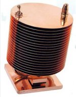
Copper heatpipe heatsink (for CPU cooling) for each amp chip, ganged in a single row and single fan cooled
What I'm thinking on doing is pair up in 3s. One pair for the tweeters, one pair for the midranges and one pair for the woofers. Each pair having their 40 000 uf filter supply (since they come preassembled as such). Only thoughts on this is that I'd like to double two chip board pairs for extra power for the woofer section (100W at 8 ohm - at 35 V rail). Problem is I can't find any info on the feasibilty of bridging to preassembled chip boards. Anyone 😕
Ben
This is a great thread as I am at the starting point of a 6 ch amp specifically to drive a pair of 3 way speakers. What is more, I might marry a Behringer DCX2496 active crossover with the amp. Connecting the output directly to the amp input stage. Remove a whole set of patch cords all together.
On my list so far I'm going with:
Pre assembled LM3886 Amplification Kit /Filter eliminator supply (x6)
Avel toroid either 330 VA or 500 VA with 25 V secondaries (x1)
Copper heatpipe heatsink (for CPU cooling) for each amp chip, ganged in a single row and single fan cooled
What I'm thinking on doing is pair up in 3s. One pair for the tweeters, one pair for the midranges and one pair for the woofers. Each pair having their 40 000 uf filter supply (since they come preassembled as such). Only thoughts on this is that I'd like to double two chip board pairs for extra power for the woofer section (100W at 8 ohm - at 35 V rail). Problem is I can't find any info on the feasibilty of bridging to preassembled chip boards. Anyone 😕
Ben
Attachments
- Status
- Not open for further replies.
- Home
- Amplifiers
- Chip Amps
- 5.1 Channel Chip Amp/Gainclone for Home Theater