After a lot of reading and studying schematics (and tickering with pre amps), I thought I had the basiscs down for my first class AB1 ultra linear 4x KT88 into a Hammond 1650T OPT build. My goal is between 100 and 120 watts of power, which I assume is realistic.
For some reason, after drawing all the load lines (1/2 OPT impedance for class A part, 1/4 OPT impedance for class B part, shifting up class A line for bias point), my calculations show I've only got about 81 watts of power. HT will be 500V, fixed bias around -58V, which should, according to other builds I've found, be plenty for the 100W+ goal.
In my noob-ness, I offcourse might have made some errors. Any insight is welcome.
edit: I've attached the curves with loadlines. Tubes are paralleled, so Ia should be doubled.
Last edited:
And while writing the 'edit' I might have answered my own question. For power calculations, I used around 430mA instead of the doubled 860mA. Although RMS power would then be 172W... I'm lost.
Lol... and you're worried about the difference?
The acoustic difference between 120W and 81W is only 10log(120/81) = 1.7 decibels ... in other words, almost inconsequential. I know you're trying to get all the design stuff right (laudable, I might add!) through use of curves and load lines, but really what you're going to end up doing is putting a variable bias on the tubes (though exotic... one for each tube, with separate grid-feed caps to isolate the relatively different DC bias voltages), and using a well measured cathode resistor of low value (on each KT88), measure the voltage across that cathode resistor, use ohm's law, and back-calculate the current flow. Nominal without a signal.
Adjusting the bias to get each KT88 to somewhere between the 1/10th and 1/2 nominal conduction level (follow your curves!). Then, start with some nice clean music source (or you could go signal-generator and sine waves + oscilloscope), and measure the CATHODE RESISTOR voltage (again). Why? Well because its going to be close to ground (safe), and because you know the value of each tube's resistor, you'll be able to balance the current quite nicely. And set it to the nominal value afforded by your load curves.
NOTE that in doing this, you need a 4 ohm or 8 (or whatever!) resistive load on the output transformer. This is to burn up the power that otherwise would reflect back as reverse EMF, driving the high voltage at the KT88 anodes much higher than your specification. You don't want much of that, for the life of the tubes, and your safety.
In the end, graphs and load curves get you "to the ballpark". Real tubes, with real differences in manufacturing, different days of make, different diffusions of helium through the glass-metal electrode seals, different batches of oxides for the cathode, and so on ... simply will need you to balance things by potentiometer. Carefully. Very carefully. And the load curves tell you "kind of where we should be".
Never had an amplifier that EVER "hit it" on the dot when everything was spec'd in advance, plugged in, and turned on the first time. Not even very close.
GoatGuy
PS: these "low value cathode resistors" can be something that'll give enough DC voltage with the expected current, to give you 3 digits of precision on your digital meter. Most meters of any quality today are happy measuring down to sub-1-volt and giving 3 digits. Therefore ... if the current is expected to be (say) 100 milliamps nominal (per tube, though -58Vg1 and +500Va yields like 50ma for Svetlanas) then you might want to use a 2 ohm resistor. Bypass it (or not, it won't really make much difference) with a 2000 uF 25 volt electrolytic. actually, don't. To finally "hear the full sound", just short out the cathode resistors (in place, with a bit of bypass copper wire!), to see the difference, once the biases are set.
You're welcome.
GoatGuy
You're welcome.
GoatGuy
Thanks for the extensive reply! That's a lot of useful info that will be very helpfull in the next design stages. And I will take it to heart all this theory is a guide and not an exact real world outcome 😉.
A few questions rise though; In my second post, I concluded the power ouput wasn't 80-something watt, but actualy 172. Enough to seriously saturate the xformer I assume. I forgot the use the double plate current in my calculation because of the paralle tubes, but please correct me if I'm wrong.
If my calculation of 172 watt is about right, then I wonder why there are so many schematics with similar tubes and xformers ratings. Is the excess of power used the provide negative feedback or is there another reason for this 'mismatch'?
Last edited:
After a lot of reading and studying schematics (and tickering with pre amps), I thought I had the basiscs down for my first class AB1 ultra linear 4x KT88 into a Hammond 1650T OPT build. My goal is between 100 and 120 watts of power, which I assume is realistic.
For some reason, after drawing all the load lines (1/2 OPT impedance for class A part, 1/4 OPT impedance for class B part, shifting up class A line for bias point), my calculations show I've only got about 81 watts of power. HT will be 500V, fixed bias around -58V, which should, according to other builds I've found, be plenty for the 100W+ goal.
In my noob-ness, I offcourse might have made some errors. Any insight is welcome.
edit: I've attached the curves with loadlines. Tubes are paralleled, so Ia should be doubled.
View attachment 334811
You don't get 120W because you didn't build the composite plate curves of the push-pull amp and thus the right 1/4 load-line. Have a look here for instance:
Part 3 - Of Loadlines, Power Output, and Distortion
Thanks, but I have to disagree. Merlin Blencowe and Morgan Jones, two authors I hold in very high regard, both agree composite curves are somewhat 'overkill' for drawing the power stage loadlines. Reasons being a speaker is not pure resistance and valves are not perfect. Treating half the PP output as single ended and then converting the outcome to full PP requirements is enough to create a basic picture. And this is supported when drawing up the loadlines with the given values on e.g. the Genalex KT88 datasheet for the AB1 ultra linear fixed bias configuration (98W vs 100W given in the sheet).You don't get 120W because you didn't build the composite plate curves of the push-pull amp and thus the right 1/4 load-line. Have a look here for instance:
Part 3 - Of Loadlines, Power Output, and Distortion
So the question still stands, why are there so many PPP designs with 1650T (Z=1900 a-a) type configuration and 4 KT88's while the power outputs from the valves will far exceed the xformers ratings when pushed to full signal swing?? Headroom? Keeping away from 0V on G1? Margin for NFB??
So the question still stands said:4xKT88 into Hammond 1650T, what am I missing?
1650W also Z=1900ohm a-a, best whit this transformer???
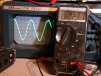
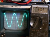
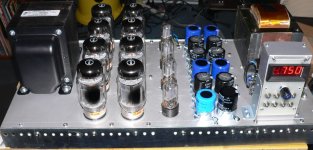
I have both transformers Hammond 1650T and 1650W , so i send 608VAC 50HZ from mains power transformer to plate to plate , secondary 8ohm on 8ohm 250W resistors, by oscilloscope and voltmeter same result, 37,5 Vac for 1650T and 38,1 Vac for 1650W, waveform exactly the same ,no saturation at all!
Last edited:
That's impressive, does the 1650T even get warm? You have ~176W, well over its spec'd 125W. But for 4xKT88, the output power would be >200W, so I'm with funk1980, how can it handle continuous power like that? The 1650W makes more sense as it's rated at 280W...
the 1650T rated 0,403A par side 120W 1K9ohm PP a 30-30KHz +-1dB
the 1650W rated 0,806A par side 280W 1K9ohm PP a 30-30Khz +-1dB
my question its maximum voltage +B and max swing PP for 1650T!
imy bass amp 8XKT120 a 600V UL 1650W give 45,7Vrms 8ohm sinusoidal,50Vrms 8ohm little distorsion.
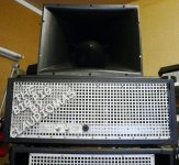
next photos chassis
the 1650W rated 0,806A par side 280W 1K9ohm PP a 30-30Khz +-1dB
my question its maximum voltage +B and max swing PP for 1650T!
imy bass amp 8XKT120 a 600V UL 1650W give 45,7Vrms 8ohm sinusoidal,50Vrms 8ohm little distorsion.
next photos chassis
Attachments
Last edited:
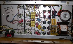
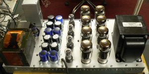
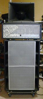
thi is a professional bass guitar amplifier, nothing else matters.Add a flat topped metal cabinet, turn it on have a cook out!
best regards
claudiomas
Last edited:
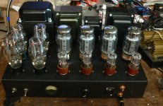
That's one mean machine - must shake the ground when you play! What's the control display on the right hand side?
I have both transformers Hammond 1650T and 1650W , so i send 608VAC 50HZ from mains power transformer to plate to plate , secondary 8ohm on 8ohm 250W resistors, by oscilloscope and voltmeter same result, 37,5 Vac for 1650T and 38,1 Vac for 1650W, waveform exactly the same ,no saturation at all!
You are not seeing saturation for 2 reasons.
1) magnetic saturation is highest at the lowest frequency rated .
Didn´t read the Hammond datasheets but I bet they specify a much lower than 50 Hz frequency limit (20 Hz? ... 30 Hz? ... dunno) so at 50Hz they are still relatively coasting along, quite far away from magnetic saturation.
2) saturation in a transformer is not the same as saturation/clipping in an amp stage, which abruptly squashes the waveform and is VERY visible.
And unless you take some extra steps, so far you are seeing a *voltage* waveform.
a) magnetic saturation in a transformer takes the form of a loss of permeability , so a loss of inductance.
At low frequencies transformer impedance will fall and it will take more current from the generator driving it.
But if the generator is low impedance (a PT is so, by definition), the current waveform will increase but the voltage will keep steady so the voltage waveform will not change (what you observed on scope screen) .
If you want to perform the proper test, put a small resistor in series with ground end of primary of OT under test, clip a scope probe across it to have a primary current waveform and send it to the X channel, then other probe end to end to secondary to see transferred voltage , connect it to the Y scope channel and set it to XY display.
In a perfect World you´d see a straight line, but in practice you will both see phase shift and nonlinearity.
Which might be acceptable at 50Hz but will definitely be visible at, say, 30 Hz.
And that measurement is important because tube plates are not voltage sources by any means, but high impedance ones, increasing distortion/nonlinearity.
Or to be more precise, not compensating/hiding it.
bias voltmeter, switch and bias trimmers for 8 the output tubesThat's one mean machine - must shake the ground when you play! What's the control display on the right hand side?
Attachments
super interesting, so for 1650T its better a very good tube choke input power supply for 400V+B and 4 KT88 will sound very nice for HiFi120Watts max power, right? 1650W better for bass guitar!You are not seeing saturation for 2 reasons.
1) magnetic saturation is highest at the lowest frequency rated .
Didn´t read the Hammond datasheets but I bet they specify a much lower than 50 Hz frequency limit (20 Hz? ... 30 Hz? ... dunno) so at 50Hz they are still relatively coasting along, quite far away from magnetic saturation.
2) saturation in a transformer is not the same as saturation/clipping in an amp stage, which abruptly squashes the waveform and is VERY visible.
And unless you take some extra steps, so far you are seeing a *voltage* waveform.
a) magnetic saturation in a transformer takes the form of a loss of permeability , so a loss of inductance.
At low frequencies transformer impedance will fall and it will take more current from the generator driving it.
But if the generator is low impedance (a PT is so, by definition), the current waveform will increase but the voltage will keep steady so the voltage waveform will not change (what you observed on scope screen) .
If you want to perform the proper test, put a small resistor in series with ground end of primary of OT under test, clip a scope probe across it to have a primary current waveform and send it to the X channel, then other probe end to end to secondary to see transferred voltage , connect it to the Y scope channel and set it to XY display.
In a perfect World you´d see a straight line, but in practice you will both see phase shift and nonlinearity.
Which might be acceptable at 50Hz but will definitely be visible at, say, 30 Hz.
And that measurement is important because tube plates are not voltage sources by any means, but high impedance ones, increasing distortion/nonlinearity.
Or to be more precise, not compensating/hiding it.
just ready one mono block by 1650T, 4X KT120 output 31V rms /8ohm =120Watts perfects
from 20 to 30KHz, sound very nice, bass powerfull and voice its just really great,
i'm goin to built one other for stereo, also i have 1 spare 1650W,
ask for measurement if you like,
cheers
claudio
from 20 to 30KHz, sound very nice, bass powerfull and voice its just really great,
i'm goin to built one other for stereo, also i have 1 spare 1650W,
ask for measurement if you like,
cheers
claudio
Attachments

- Status
- Not open for further replies.
- Home
- Amplifiers
- Tubes / Valves
- 4xKT88 into Hammond 1650T, what am I missing?