These are from something I did 10years ago (or more).
I would probably do things a little different today.
The document is some notes on the design and some test results.
The pdf is teh amp schematic.
The jpg is the power supply schematic.
"DUD" is a bit of poking fun at myself - stands for "Down Under Designs".
Cheers,
Ian
I would probably do things a little different today.
The document is some notes on the design and some test results.
The pdf is teh amp schematic.
The jpg is the power supply schematic.
"DUD" is a bit of poking fun at myself - stands for "Down Under Designs".
Cheers,
Ian
Attachments

my power amps are just based on more traditional GEC multipair 400watts,
whit valves power supply for Hi-Fi, sound beautyfull.
only the power supply its different from Woodville schematics.
450/0/450VAC supply 4X 5C3S (5U3C)
the main choke its 5H 500mA for +B 530V a rest and 480V a full power,
it was too small for choke filter so i need to put 47uF/900V (conbination =// of 4X 47uF-450V) on head before and two siemens 390uF/450V // (195uF-900V) for +B , followed by 20H 100mA for 450V +B2 splitter and 10H50mA for 250V +B3 class A input tube .
for -B G1 silicon bridge and BC 200uF/200V and Roderstein 470uF/100V.
i like very much the splitter for yours amp, can you develop please, any measurement photo a low frequency below 100 Hz???These are from something I did 10years ago (or more).
I would probably do things a little different today.
The document is some notes on the design and some test results.
The pdf is teh amp schematic.
The jpg is the power supply schematic.
"DUD" is a bit of poking fun at myself - stands for "Down Under Designs".
Cheers,
Ian
my next amp will have different splitter, the GEC cathodyne its a little poor!
Attachments
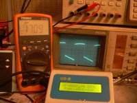

balanced XLR 100Hz square and 30Hz sinu from pro CF recorder, much better, directly bypass cathodyne splitter
Attachments

Last edited:
That ringing on the 100Hz squarewave...is a sign of trouble and requires a bit more circuit examination, esp the schematic. Even the 30Hz on the tips is suspect.
this RINGING come from FLASH CARD RECORDER not from the amp, just forThat ringing on the 100Hz squarewave...is a sign of trouble and requires a bit more circuit examination, esp the schematic. Even the 30Hz on the tips is suspect.
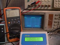
the last two photos are from balanced line bypassing input and splitter,
my signal generator only unbalanced output.
difference from unbalanced and balanced 100 Hz its evident
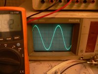
the sinus 30Hz a 50% power supply its much better in balanced mode,
the cathodyne splitter its not perfect at very low frequency
Well, first you have to realize it's a mono block, so you'll need two of them 🙂
Personally, I would simplify a few things:
- Get rid of the recitifier tubes and just use solid state diodes
- Remove V6A/V6B (cathode followers). You won't go AB2. Not necessary and saves a tube.
- 10k gridstopper seems a bit excessive for V4A. Adds white noise and not necessary since it's a hifi amp.
- I don't really see the point in dropping the voltage that much for V4A. Pushes the loadlines to the more non-linear regions. And with a 56uF filtercap, a 100k dropping resistor isn't required either.
- Concerning layout. The KT88's seem really close together. Datasheets state 4 inches apart, measured from the center.
That, at first glance.
Yes, I agree with funk1980, get rid of the CF, especially since the cathode voltage of 153V exceeds the 6SN7GTB's heater-cathode voltage by a wide margin, which is just asking for trouble.
Oh my God!😀Thanks, but I have to disagree. Merlin Blencowe and Morgan Jones, two authors I hold in very high regard, both agree composite curves are somewhat 'overkill' for drawing the power stage loadlines. Reasons being a speaker is not pure resistance and valves are not perfect. Treating half the PP output as single ended and then converting the outcome to full PP requirements is enough to create a basic picture. And this is supported when drawing up the loadlines with the given values on e.g. the Genalex KT88 datasheet for the AB1 ultra linear fixed bias configuration (98W vs 100W given in the sheet).
It really doesn't take too much if you just print out two plate curves pictures and match them properly for a given bias point to get the composite tube. Drawing a bunch of straight lines passing through few calculated points in the relevant working area is really easy and quick (Or I should say it's easy and quick once one knows how to do it). High accuracy is useless as datasheet curves only represent average tube and determining things on paper is not so accurate on its own, regardless SE or PP topology. You can get a very good agreement only if you have the real curves of your actual tubes and build a perfectly matching model to those.
Anyway, one thing is a proper loudspeaker for a tube amplifier and another thing is how it will behave into a variable load. No speaker is a resistive load but this doesn't mean tube amp will not work properly and no assumptions can be made to get the best out of it. A typical and properly designed PP tube amp will certainly have no trouble driving a proper tube speaker and behave as a nearly constant power source which means that for some change in secondary load (typically from 5 to 9 ohm for nominal 8 ohm load) the power delivery will not change a lot. Typically will be down or up by 10-15% respect to the nominal load in that load range. Of course this is just the typical trend and depends on the design.
The PP amp suffers much less than a SE a variable load if designed to cope with it.
Power rating of Hammond OT's is not very clear. Anyway if they are rated 120W at 30Hz then they can cope with 200W down to 38Hz. Not a big deal....So the question still stands, why are there so many PPP designs with 1650T (Z=1900 a-a) type configuration and 4 KT88's while the power outputs from the valves will far exceed the xformers ratings when pushed to full signal swing?? Headroom? Keeping away from 0V on G1? Margin for NFB??
Last edited:
Thanks, but that's a response to a post almost two years old and given the current circumstances and knowledge gained, not really relevant anymore 😀
This thread took the turn to look at other similar (relatively) high power designs.
This thread took the turn to look at other similar (relatively) high power designs.
- Status
- Not open for further replies.
- Home
- Amplifiers
- Tubes / Valves
- 4xKT88 into Hammond 1650T, what am I missing?