hi:
have a look with this circuit diagram,can it works well?
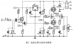
I draw this circuit diagram last night...
RP1 control the currency of output stage,set it to 50K at first;
RP2 control the voltage of ouput point(0.22V+1/2Ucc);
SK170 can replace with sk389 or NPD5564(twins);
😉
have a look with this circuit diagram,can it works well?
I draw this circuit diagram last night...
RP1 control the currency of output stage,set it to 50K at first;
RP2 control the voltage of ouput point(0.22V+1/2Ucc);
SK170 can replace with sk389 or NPD5564(twins);
😉
Attachments
DarkHorse said:can it works well?
😉
I'd take the gate resistor R8 of the top IRF510 higher --> 510k too, and add a gate resitor >> 10 ohms.
The input/driver will have reduced distortion as you take a higher Vb there, say 50V. This might be a considerable reduction. It is also something that the feedback in the way you design it, cannot correct. This means that RP1 has to increase along the way.
It does have a Pass flavour to it that is nice. Its simple. What do we want more? Well, Q4 is not really needed, and by having a resister it should work out well too methinks.
DarkHorse said:hi:
have a look with this circuit diagram,can it works well?
I draw this circuit diagram last night...
RP1 control the currency of output stage,set it to 50K at first;
RP2 control the voltage of ouput point(0.22V+1/2Ucc);
SK170 can replace with sk389 or NPD5564(twins);
😉
it is fet/mosfet version of Aikido Amplifier by John Broskie, TCJ
Upupa Epops said:4 W amp with 1.1 bias current ? What are you waiting from this " miracle " ?
hi,Upupa Epops :
4W(RMS) is 8W(peak)in sine-wave ,so load is 8ohm,and P=I^2*R,then I=1.0A,so I=1.1A is suitable!
driver stage using SE instead of using bootstrip or using hight-Voltage supply,and it can win more low distortion...
cheers
WINCO
Re: Re: 4w All Fet Class-a Amp
I don't know where this diagram from!but it's topology so simply that make me so surprise...
this is original schematic which I referenced:
😉
padamiecki said:
it is fet/mosfet version of Aikido Amplifier by John Broskie, TCJ
I don't know where this diagram from!but it's topology so simply that make me so surprise...
this is original schematic which I referenced:
😉
Attachments
If you take this connection as excercise, so go on. But with four transistors don't wait miracles, although they are relatively modern ones, all is too simply 😉 .
Upupa Epops said:If you take this connection as excercise, so go on. But with four transistors don't wait miracles, although they are relatively modern ones, all is too simply 😉 .
haha:
yes,I understand your meaning.
but as a small "kid"(only 4W output power),it's capability was enough strong,THD=0.15%,phase angle is +0.2 degree(20Hz) and -0.7 degree(20KHz).I think it is so great...
all for it's simply.I like it,and hope it's sound can sweet than ZEN2(the class-a amp I have alread build)..
Attachments
Fuling said:Note that the original circuit is a transconductance amp (current feedback).
hi:
yes,I have note this problem.
current FB is can cut-off the speaker's reverse voltage...
but distortion is too XXX(4%).
see you tomorrow.
Re: Re: Re: 4w All Fet Class-a Amp
you are right
my look was too quick
I have mismatched it with mentioned TCJ
DarkHorse said:
I don't know where this diagram from!but it's topology so simply that make me so surprise...
this is original schematic which I referenced:
😉
you are right
my look was too quick
I have mismatched it with mentioned TCJ
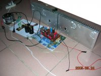
I will build a sample to examine the sound class of this circuit,wait for my report please!about the day after tomorrow...I show you.
enjoy!

enjoy!
There are substantial differences between yours and the original design but I like yours better.
Yours has the gain in the first and 2nd stages: both are drain-loaded-with-CCS and with global feedback. The original is a source-follower, followed by a drain-loaded with CCS for gain, without any feedback.
It is my experience that it is easier to have gain with small signal. So I was wondering if you can improve upon your design by using a source-follower in the 2nd stage (source follower + CCS).
You can then limit the feedback to the first stage as well (you can look into the Zen to see how to implement feedback in the first stage).
Let me know what you think.
I bet this would sound great with some high effeciency speakers. There is a lot you can do with 4 wrms a chan.
http://www.selectronic.fr/upload/produit/fichetechnique/7480SM.pdf
schematic like this :
but with gain and current feedback
a Zenquito without driver ...
schematic like this :
An externally hosted image should be here but it was not working when we last tested it.
but with gain and current feedback
a Zenquito without driver ...
An externally hosted image should be here but it was not working when we last tested it.
tlf9999 said:There are substantial differences between yours and the original design but I like yours better.
Yours has the gain in the first and 2nd stages: both are drain-loaded-with-CCS and with global feedback. The original is a source-follower, followed by a drain-loaded with CCS for gain, without any feedback.
It is my experience that it is easier to have gain with small signal. So I was wondering if you can improve upon your design by using a source-follower in the 2nd stage (source follower + CCS).
You can then limit the feedback to the first stage as well (you can look into the Zen to see how to implement feedback in the first stage).
Let me know what you think.
hi,tlf9999:
At first I really don't know would it sounds better than the original version, because global feesback can cause other unexpectable problem...maybe it just decrease distortion in parameter..low distortion not mean it can sounds well..and I am so afraid the speaker's reverse voltage loop back and effect the first gain stage..
I don't want to use source-follower,I think IRF510's C-input is 180pF,driver current in 10mA is suitable.too strong driver stage perhaps let sound comes too "hard"(not sweet),I think..
but if you want use IRF530 or IRF540..this source-follower is needed to high frequency(10KHz or more)..
DJNUBZ said:I bet this would sound great with some high effeciency speakers. There is a lot you can do with 4 wrms a chan.
hi,DJNUBZ:
in fact,this circuit can output 4.5W(RMS) with 1.1A bias current.
have fun!
WINCO
😀

Hi Ultimate86,
Your circuit looks like a Le' Monstre variation. Have you build those?
Regards,
Ipanema
Your circuit looks like a Le' Monstre variation. Have you build those?
Regards,
Ipanema

- Status
- Not open for further replies.
- Home
- Amplifiers
- Solid State
- 4w All Fet Class-a Amp