
Ipanema said:Hi Ultimate86,
Your circuit looks like a Le' Monstre variation. Have you build those?
Regards,
Ipanema
I built a Zenquito, which is a kind of evolution with MOSFET of "Le Monstre"
http://www.bonavolta.ch/hobby/en/audio/monster.htm
l http://perso.wanadoo.fr/jm.plantefeve/home.htm
ProFet that I proposed has neither cascode nor driver !
Just Jfet input + Mosfet output ... but I do not have the complete diagram
hi,all:
I test it last night.
it works abnormality ,that is to say---it doesn't works well,
result show it has about 0.5Hz surge,because first stage's low frequency gain is too strong,R3 should not connect to feedback loop,it's positive feedback...
so I decide to use other bias way(SK170's)...
look it's ac analysis graph:
Attachments
Take it easy!I will go on tonight,it has more suitable topology,and lower distortion...I believe it can sounds perfect!
the test in last night,I relocate R3(down end) connect to ground.
the surge problem removed,but the output point of first stage upto about 14V,no matter what,it sounds,and sounds pretty good,I can't hear any noise from the speaker,I only use one 10000uF/50V cap and shunted with one 10uF/100V MKP cap,
ouput stage's bias current is about 1A..
step by step,I walk to success...haha
this is updated version of schematic:
😀
Attachments
padamiecki said:cheers!
could you unconnect nfb and describe the sound after deconnecting?
hello, padamiecki :
nfb???
it's hard to say that now,but I will tell you tomorrow!
regards
WINCO


fail again!!!
the super low surge(0.5Hz) still existing!
I suppose it's open loop gain rate is too high,and the feedback is too deep,so it occur...isn't it???
last night,after the failed testing..I had to remove the Q4 and RP3,
replace with one resistor,the value is 1Kohm...it sounds:
the sound is so soften and sweet,put my ear close to the loud speaker,about 0.3 meter(1'),I only hear the heat noise of semiconductor device..no 50Hz low frequency noise---good!
sound quality is more than my ZEN2,I hear Michael Jackson's "billie jeans"...you can lisend it for a long time,didn't feel any uncomfortable and any noisily...
I will go on!😡
UltimateX86 said:
I have used he same circuit,
but without nfbes,
even local
my posts should be somewhere here in solid state forum
but for some person the sound was too weak.
With nfb connected the sound becamed nervous.
padamiecki said:
I have used he same circuit,
but without nfbes,
even local
my posts should be somewhere here in solid state forum
but for some person the sound was too weak.
With nfb connected the sound becamed nervous.
hi:
your "nfb" is means "globe feedback"?
I think "nfb"is "none globe feedback".
but not all "globe feedback" connect would make sound became nervous,only occur on which circuit using high power transistor(with big input capacitor,as if IRF044,IRF140..),and amp has high gain rate,and deep feedback loop,this C-input will effect the sounds,phase compensator almost using a cap(10pf---47pf) shunts with feedback resistor,lead to "TIM" distortion...
I think if the output transistor(IRF510) has small C-input,it's effect will reduce more,and it can sounds sweet too...
cheers!
WINCO
😉
DarkHorse said:
I think if the output transistor(IRF510) has small C-input,it's effect will reduce more,and it can sounds sweet too...
cheers!
WINCO
😉
maybe, who knows?

padamiecki said:
I have used he same circuit,
but without nfbes,
even local
my posts should be somewhere here in solid state forum
but for some person the sound was too weak.
With nfb connected the sound becamed nervous.
what is certain, it is that French likes it
UltimateX86 said:
what is certain, it is that French likes it
so maybe is there in the world a definition "The French sound?"
Here is my variation.
It is essentially the same front end as DarkHorse's design. Except that in the 2nd stage, rather than using a drain-loaded output stage with gain, mine is a source follower.
Simulated quite well, and harmonics are mostly 2nd, 3rd and 4th, with the 2nd harmonics dominating.
Warning: conceptual design, never meant to be built, not optimized.
Attachments
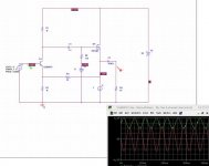
One quick comment: the feedback pick-up point (right side of R3) can be at either the MOSFET's source or on the load.
Hi DarkHouse
You MUST NOT load a collector or drain follower with a current source when there is no way that global feedback sets your DC operating point. This is a no no and only works in simulation. . Both FETs are not equal. Use a resistor instead. Maybe this is also the problem for your 0.5 Hz surge
but the output point of first stage upto about 14V,no matter what
You MUST NOT load a collector or drain follower with a current source when there is no way that global feedback sets your DC operating point. This is a no no and only works in simulation. .
Both FETs are not equal. Use a resistor instead. Maybe this is also the problem for your 0.5 Hz surgebocka said:Hi DarkHouse
You MUST NOT load a collector or drain follower with a current source when there is no way that global feedback sets your DC operating point. This is a no no and only works in simulation. .
hi,bocka:
yes, you are right!I remove R14 away,the circuit can works well,and I have try 10Kohm /7.5Kohm /5.1Kohm of R14,I find R14 must large than 5.1Kohm that the circuit can works!
let's see the last passed test circuit:
Attachments
- Status
- Not open for further replies.
- Home
- Amplifiers
- Solid State
- 4w All Fet Class-a Amp