Recently I obtained an old chassis and after restoration it gave a pleasant, lifely 4-5W. Here's the schematic:
The cathode connection struck me as odd because both posive and negative feedback is applied. I don't get it.
Furthermore bass is not very deep, I'd guess below 50Hz is non existant. Raising the value of C1 (and C2 while lowering R7) didn't bring happiness. I wonder if someone can model the stage preceding T2 for bandwidth. The OPT is heavy but it's quite ancient, I have no specs for it. Another suspect there 😉
An externally hosted image should be here but it was not working when we last tested it.
The cathode connection struck me as odd because both posive and negative feedback is applied. I don't get it.
Furthermore bass is not very deep, I'd guess below 50Hz is non existant. Raising the value of C1 (and C2 while lowering R7) didn't bring happiness. I wonder if someone can model the stage preceding T2 for bandwidth. The OPT is heavy but it's quite ancient, I have no specs for it. Another suspect there 😉
The positive feedback via R11 will lower output impedance - perhaps needed with a pentode output.
The 22k output grid stopper may suggest that this was not intended as a hi-fi amplifier, as smaller values are more commonly used. The OPT might not have a particularly wide bandwidth.
The 22k output grid stopper may suggest that this was not intended as a hi-fi amplifier, as smaller values are more commonly used. The OPT might not have a particularly wide bandwidth.
22n/22k is probably the way to make "farting" distortions less audible (i.e. dynamic distortions caused by non-linear grid currents, especially when bass is amplified like in this particular case). Positive feedback by current and negative feedback by voltage increase damping factor of a speaker, up to the negative output resistance. But it is wideband that is not needed, though simple to implement.
An externally hosted image should be here but it was not working when we last tested it.
An instrument amplifier? The EI76 output and banana plugs suggested otherwise. Oh well..
It's intended for line level alright. Settled for these changes: R6 -> 1K5, R7 -> 220K, C2 -> 100nF. Bass is adequate now, the tone control works excellent, no excessive hiss or hum.

Each and every capacitor was bad, the rectifier blown, some resistor values off by 50%. It's playing not bad for a salvaged disposal, would recommend this schematic if you have a 325/300V psu for 80mA. Not state of the art of cause but low tech holds its own charm (sometimes) 🙂
An externally hosted image should be here but it was not working when we last tested it.
Each and every capacitor was bad, the rectifier blown, some resistor values off by 50%. It's playing not bad for a salvaged disposal, would recommend this schematic if you have a 325/300V psu for 80mA. Not state of the art of cause but low tech holds its own charm (sometimes) 🙂
That tube doesn't look like a 4699 ? Rather a EBL21 , will not live very long in this config. unless you adapt the cathode resistor.
Mona
Mona
Interesting. I believe I read somewhere, possibly in an old AudioXpress, that adding positive feedback to increase gain before adding negative feedback has a net effect of reducing distortion more than negative feedback alone because it forces the first tube to operate over a smaller and therefore more linear portion of its input range. Some Dynaco products also use this trick.
The output tube is generally where most of the distortion originates. So not a good place to put a positive feedback loop. Usually one would want to put the positive feedback loop around an earlier, lightly stressed (lightly loaded), voltage amplifier stage.
The positive feedback loop in this design is more oriented toward cancelling winding resistance in the OT, as Wavebourn mentioned. R5 samples the output current, and R11 feeds back a boost signal to increase the drive voltage for T2, to compensate for voltage loss across the winding resistance in the OT.
Not perfect however, since T3 is not providing the most linear gain here, due to significant loading.
One can extend the technique to cancel out leakage reactance in the OT as well.
 Don - posting with multiple user ID's is not allowed, so the Tube9fromHelll account will be disabled, please post under your old user account.
The ones I remember had bakelite base.These look more like a mix of the old base and a locktal.Strange 😕Most 4699 I have look like that.
Only a few very old ones are ST shaped.
Mona
Attachments
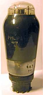
The ones I remember had bakelite base.These look more like a mix of the old base and a locktal.Strange 😕
Mona
It seems that with the tubular shape they also introduced the metal collar above the base.
Here are the 4699, 4699N, 2xEL60 and their final descendant the EL34.
Attachments
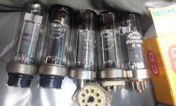
At the left the original pre war shape. Later 4699 had different heaters, labelled 4699N. At the right is an EL6 with identical properties as 4699N. Good ones are getting scarce rapidly...
An externally hosted image should be here but it was not working when we last tested it.
Last edited:
Yep, many types of that period have the anode metal in common. Its physics is probably unsurpassed. Here's one more:.. Once in the socket they look the same 😕
Mona
An externally hosted image should be here but it was not working when we last tested it.
FFR see Die EL-34-Story
Last edited:
While still under the specified 425V max, the screen is on 20V higher potential then the anode. Is there a penalty in doing so?
feedback!
Boy this is a nice find. What wasn't immediately clear the opt has an UL tab, at 50%. Driving the 4699 directly from my CDP sounded darn good rightaway. Just one tube, imagine.
Because the powertube is biased at 8,6V I'm missing a little amplification. So, in came an ECC88 (6DJ8) and feedback. Now I'm strugling with theory and calculation to get it right. Can someone point me in the right direction? At low volume music plays fine but at higher setting it muffles / sounds compressed.
nb R1 is little too high, aimed anode voltage is 100V, cathode 2,0V (10mA).
An externally hosted image should be here but it was not working when we last tested it.
An externally hosted image should be here but it was not working when we last tested it.
I gave T1 cathode more breathing space by adjusting R2 and lowered FB by upping R12. That's better. I still don't get how the ratio R2/R3 effects the amount of FB and how a bypass cap would interact.
An externally hosted image should be here but it was not working when we last tested it.
To a first approximation the ratio R2/R3 does not affect the amount of feedback. Feedback is just R3/(R12+P2+R3).disco said:I still don't get how the ratio R2/R3 effects the amount of FB and how a bypass cap would interact.
A better approximation takes account of second order effects. You have to calculate the resistance seen at the junction of R2 and R3. This is R3, in parallel with R2 plus the cathode impedance. The cathode impedance will be 1/gm plus anode load/mu (or mu+1 - I can't remember and it doesn't really matter anyway). Anode load, to a first approximation is R1 (but strictly we ought to include the effect of R7 in parallel - and don't mention capacitance!). Let's be good and use R1'=20k.
So we have R2' = R2 + 1/gm + R1'/mu. R2' is then in parallel with R3 to get R3'. Feedback is then R3'/(R3' + P2 + R12).
- Status
- Not open for further replies.
- Home
- Amplifiers
- Tubes / Valves
- 4699 SEP (unusual cathode feedback?)