A better approximation takes account of second order effects. You have to calculate the resistance seen at the junction of R2 and R3. This is R3, in parallel with R2 plus the cathode impedance.
Thanks Dave, I owe you a cigar.
So, lowering cathode impedance would increase FB only marginally as R3 << R2 + cat imp.
On the other hand, removing local feedback over R2 with a bypass cap would result in higher amplification.
Time for experiments 😀
Last edited:
Bypassing R2 gives higher loop gain, and slightly smaller feedback so slightly higher closed-loop gain. If you were unlucky you could get reduced loop stability. Try it, and see what happens.
High open loop gain is what we want to apply FB. Without the R2 bypass square waves look not so clean. Could the OPT benefit from a zobel over it?

Looking at it again, you aren't using hardly any feedback at all I don't think, might as well disconnect it.
Correct me if I am wrong, open loop gain~24?
Substitute an 820 ohm resistor for R12 and that should give you -6db loop gain.
Since there is a 50% tap maybe it's a push pull transformer? That would explain the poor bass.
Correct me if I am wrong, open loop gain~24?
Substitute an 820 ohm resistor for R12 and that should give you -6db loop gain.
Since there is a 50% tap maybe it's a push pull transformer? That would explain the poor bass.
That might depend on whether you are seeing OPT ringing or the onset of loop instability.
Yes, but tests are on hold for today... 😡 😛
An externally hosted image should be here but it was not working when we last tested it.
Looking at it again, you aren't using hardly any feedback at all I don't think, might as well disconnect it.
Correct me if I am wrong, open loop gain~24?
Substitute an 820 ohm resistor for R12 and that should give you -6db loop gain.
Since there is a 50% tap maybe it's a push pull transformer? That would explain the poor bass.
Bass is fine, no complaints there, and it's really a SE 😀
Open loop gain of 24, that might be right.
Closed loop is 5 or thereabout. I measured 3 with the volume pot at two 'o clock.
NFB should be part of the design process. The best amount of NFB is the correct amount for that circuit; less or more could degrade things.
I suppose you could set NFB with a scope by looking for ringing on a square wave and reducing NFB until the ringing disappears. Not a good method, as you can't distinguish between too much NFB and too little compensation.
Using a dual-channel oscilloscope, display the input and output signal of the amplifier without feedback. Use an audio signal generator as input. Find the frequencies where the output is opposite phase to the input, that is 180 degrees phase shift. You can apply as much NFB that the closed-loop gain is < 1 at this frequency. Otherwise it will oscillate.
Up and running again; one of those Rifa timebombs went off..
Monitoring a 40Hz sinus presented at the penthode grid, the top half flattens out from 4,5Vrms on, no matter what feedback I run to the triode.
An externally hosted image should be here but it was not working when we last tested it.
Monitoring a 40Hz sinus presented at the penthode grid, the top half flattens out from 4,5Vrms on, no matter what feedback I run to the triode.
The flattening of the top half is a result of a too high signal level applied to the penthode. The driver stage has simply too much amplification (ca 48dB). My assumption was wrong that the extra amplification could be used completely for feedback. I need ca. 11dB for full power output, 37dB feedback is unpractical 😀
From back to front: the penthode needs 15Vpp. The driver must deliver 15,0/5,6=2,68 times amplification. Add another 4 times for feedback (12dB) so we're looking for a driver stage with a gain of 7. Further requirements would be low output impedance / high slew rate. I'm searching for candidates.
From back to front: the penthode needs 15Vpp. The driver must deliver 15,0/5,6=2,68 times amplification. Add another 4 times for feedback (12dB) so we're looking for a driver stage with a gain of 7. Further requirements would be low output impedance / high slew rate. I'm searching for candidates.
Last edited:
Did you try removing 4699 cathode bypass cap?
My Sim shows the same thing. Removing the ECC88 cathode bypass cap and increasing negative feedback helps. Or removing the 4699 cathode bypass cap resolves it.
My Sim shows the same thing. Removing the ECC88 cathode bypass cap and increasing negative feedback helps. Or removing the 4699 cathode bypass cap resolves it.
I have not because amplification of the driver is way out of proportion (37dB within the FB loop).
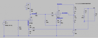
Instead I've built this:
The scope gave a normal sinus of 13Vrms with 2Vrms input. Yet another bug turns up: does the CDP give out 2Vrms? I have to turn up the volume completely for max volume. It sounds very good though. I expected to find max volume at 12 'o clock, before distortion sets in.
Instead I've built this:
An externally hosted image should be here but it was not working when we last tested it.
The scope gave a normal sinus of 13Vrms with 2Vrms input. Yet another bug turns up: does the CDP give out 2Vrms? I have to turn up the volume completely for max volume. It sounds very good though. I expected to find max volume at 12 'o clock, before distortion sets in.
Last edited:
Is it a linear taper pot or log?
Edit: How were you getting 37db from the ECC88? That tube only has a mu=33?
Edit: How were you getting 37db from the ECC88? That tube only has a mu=33?
Last edited:
it amplifies 16 times, hence 48dB in total.
I am still confused here.
First stage gain unbypassed ~16
Second stage gain is ~24
Transformer turns ratio 24:1
First stage gain is 24db
Total amp gain is 24db
This is all closed loop, if you open the feedback loop it is relatively unchanged unless you reduce the value of R12. This related to the older schematic with feedback and ECC88.
Refering to the ECC88 version: 0,31Vrms in gives 4,94Vrms out (at C1). That's 16X, according to Audio Handbook #2 (Crowhurst, 1952) 48dB. Where do we differ? 😀
The final has 5,3Vrms in and 4,7Vrms out (at the speaker terminal).
I'm still confused by the output level of a CDP, that's standard 2Vrms, is it not?
The final has 5,3Vrms in and 4,7Vrms out (at the speaker terminal).
I'm still confused by the output level of a CDP, that's standard 2Vrms, is it not?
Last edited:
Refering to the ECC88 version: 0,31Vrms in gives 4,94Vrms out (at C1). That's 16X, according to Audio Handbook #2 (Crowhurst, 1952) 48dB. Where do we differ? 😀
That is exactly where we differ 😉
(log16)*20=24.08db
The final has 5,3Vrms in and 4,7Vrms out (at the speaker terminal).
Given the OPT is 4k6 then the 4699 stage has slightly less than 24x gain or losses in iron.
I'm still confused by the output level of a CDP, that's standard 2Vrms, is it not?
I have an older one that only puts out 1.2v peak, there is a good degree of variances between models and brands from the little testing I have done.
Ok, I'll stick a probe in that ol'Sony.
See what I mean?
See what I mean?
An externally hosted image should be here but it was not working when we last tested it.
An externally hosted image should be here but it was not working when we last tested it.
- Status
- Not open for further replies.
- Home
- Amplifiers
- Tubes / Valves
- 4699 SEP (unusual cathode feedback?)