Just export it as a jpg or png file and post in the thread using the forums picture attachment service.
got it
get it
regards
http://www.diyaudio.com/forums/attachment.php?attachmentid=231137&stc=1&d=1310639102
Attachments
Last edited:
It seem to be a protel board file, which is useless to most on this forum.
I did ask you to export the board layout as a JPG or a PNG image file since thats much more useful to us.
I did ask you to export the board layout as a JPG or a PNG image file since thats much more useful to us.
It seem to be a protel board file, which is useless to most on this forum.
I did ask you to export the board layout as a JPG or a PNG image file since thats much more useful to us.
i tried to but becouse of some windows problems i couldnt. you will have it soon.
regards
that is a sorry excuse of a pcb my friend .... it has all the classical mistakes software will make when asked to design a board
a 12 year old can do better .....
dont understand what is the mess around this circuit ...
a 12 year old can do better .....
dont understand what is the mess around this circuit ...
 The pictures of the PCB are a wee bit on the small side.
And nobody seems to care that the biasing is suboptimal. Might as well stick another diode or two in that OPS and make it a class A amp, since it is just one out-of-spec component away from being one.
Last edited:
that is a sorry excuse of a pcb my friend .... it has all the classical mistakes software will make when asked to design a board
a 12 year old can do better .....
dont understand what is the mess around this circuit ...
i am actually 11 years old dude. maybe thats why.

here around everyone knows how to get a pcb out of a protel desing file(#21) and make it ok.
i dont know if it is my problem or yours but i havent heard of people having problems with protel files. have yah....


Last edited:
And nobody seems to care that the biasing is suboptimal. Might as well stick another diode or two in that OPS and make it a class A amp, since it is just one out-of-spec component away from being one.
sorry my friend . these days i am having some fin... problems and i dont have my brain turned on. BIG pcbs you will have soon.
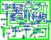
Is this ok?
I hope this may help....
check the pcb its not yet tested.ived just finished it yesterday.
check if my idea of prevention of thermal runway is correct.and open for any suggestion.
thank you.
And nobody seems to care that the biasing is suboptimal. Might as well stick another diode or two in that OPS and make it a class A amp, since it is just one out-of-spec component away from being one.
I hope this may help....
check the pcb its not yet tested.ived just finished it yesterday.
check if my idea of prevention of thermal runway is correct.and open for any suggestion.
thank you.
Attachments
well not realy importand if 11 or 12 ...it is simple like that :
you are a member in a wonderfull forum where people enjoy to share ideas ,knowledge ,help and often a few jokes .... only thing need to do is to use the search function of the forum and zillion of posts regarding pcb mistakes and how case sensitive might be an sziklai circuit regarding pcb
obviously you havent done that yet ... it will require a lot of reading ... but you will find all you need for free and with a lot of details...it will only consume time ....but if you are 11 then obviously you have a lot of this also .
Drowranger .....
i could never design such a pcb with so nice graphics .... the presentation is almost professional ... but need to ask a question .... does your software also say the behaviour of a ground plane versus the specific amplifier ? can also your software calculate inductance or capacitance between traces with such a proximity ?
i am pretty sure that your "presentation" is a result of a few hours of work ..then it could be better if your such nice graphic skills where followed by design rules for audio pcb / for amplifiers / for sziklai amplifier circuits ...
Kind regards
sakis
Last edited:
with regards to pcb design im just a newbie.im not aware if my software is capable of that im using eagle5.6.i got tips from randy sloans book about proper wirings i know its not sufficient but if you think you can put something on this design im willing to listen.is that cf design?
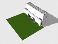
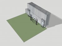
my friend did the 3d design and were doing it just for fun and to help others as you have said this is a wonderful forum where people share ideas, knowledge and even resources.
my friend did the 3d design and were doing it just for fun and to help others as you have said this is a wonderful forum where people share ideas, knowledge and even resources.
well .... then ...if you said that you are a newbie then you must be twice as much working with caution aboutr things that you are not aware of ...
the P3a Is a very well documented project that is based on the same topology ..... work with this project it will sound better ita has ready made pcb if you wish to buy but also there is at least another 10-20 pcbs made by others in the forum that are completelly free to copy ...some of them are actually very nice ...
i am not trying to suggest this next to that ... only as i said the project has a zillion of threads and posts with amazing tips on them plus that each and every detail has been worked over again and again
kind regards sakis
well not realy importand if 11 or 12 ...it is simple like that :
you are a member in a wonderfull forum where people enjoy to share ideas ,knowledge ,help and often a few jokes .... only thing need to do is to use the search function of the forum and zillion of posts regarding pcb mistakes and how case sensitive might be an sziklai circuit regarding pcb
obviously you havent done that yet ... it will require a lot of reading ... but you will find all you need for free and with a lot of details...it will only consume time ....but if you are 11 then obviously you have a lot of this also .
Drowranger .....
i could never design such a pcb with so nice graphics .... the presentation is almost professional ... but need to ask a question .... does your software also say the behaviour of a ground plane versus the specific amplifier ? can also your software calculate inductance or capacitance between traces with such a proximity ?
i am pretty sure that your "presentation" is a result of a few hours of work ..then it could be better if your such nice graphic skills where followed by design rules for audio pcb / for amplifiers / for sziklai amplifier circuits ...
Kind regards
sakis
sakis, you missed a very important point.
LEARN BY DOING.
I.e let him find out for himself why the design has shortcomings.
It is never a good idea to rely only on what others say on any forum. By all means review it, consider it and digest it, but you will learn much more from your own experiments.
I was 11 when I was given a soldering iron for passing an exam - I've worn our many iron tips since then and probably used enough solder to reach the moon!
BM
The schematic shown in this thread i'd modify to a standard class ab and remove that shady op transistor rail current drive.
well .... then ...if you said that you are a newbie then you must be twice as much working with caution aboutr things that you are not aware of ...
the P3a Is a very well documented project that is based on the same topology ..... work with this project it will sound better ita has ready made pcb if you wish to buy but also there is at least another 10-20 pcbs made by others in the forum that are completelly free to copy ...some of them are actually very nice ...
i am not trying to suggest this next to that ... only as i said the project has a zillion of threads and posts with amazing tips on them plus that each and every detail has been worked over again and again
kind regards sakis
im not aware that there is another thread for this amp.can you give me the title for this one so i can read and may be correct my mistakes.as they said much better if i learn from my mistakes rather than copy.
p3a
Got it.
well .... then ...if you said that you are a newbie then you must be twice as much working with caution aboutr things that you are not aware of ...
the P3a Is a very well documented project that is based on the same topology ..... work with this project it will sound better ita has ready made pcb if you wish to buy but also there is at least another 10-20 pcbs made by others in the forum that are completelly free to copy ...some of them are actually very nice ...
i am not trying to suggest this next to that ... only as i said the project has a zillion of threads and posts with amazing tips on them plus that each and every detail has been worked over again and again
kind regards sakis
if there is a p3a a modified of this amplifier,it doesnt mean that this amp could be disregarded. its up to the constructor which pleases him.if you find fault in my design pcb then what happens to this wonderful forum where it shares knowledge and help each other.
just joking my friend.
Actual size
I hope this may help....
check the pcb its not yet tested.ived just finished it yesterday.
check if my idea of prevention of thermal runway is correct.and open for any suggestion.
thank you.
Attachments
ok then ...here is some fast food details ...
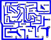
----amplifiers are not RF devices nor power supply there is a serious chance that the ground plane you made causes trouble
----if you decide to stay with a ground plane after all as seen from your pictures proximity of ground plane between traces is way too close ... that might cause inductunce or capacitance with other traces and drive the amplifier to oscilation
---- next option will be to have a star ground on board
---- you have missed decoupling and bypass of rails on the pcb .... for this type of amplifier that might help a lot ...
---- " curent source" for LTP Q3 need to be as close is possible
--- since you made the pcb with LTP tansistors close enough you might as well bring them even closer so thermal coupling and matching will also add some quality more to the amp
---- C3 feedback capacitor is not MKP cap ...its an electrolytic ou have used the wrong part
---- Finally thermals is a quiet serious issue on this amplifier since no output resistors are used ...beyond serious heatsinc the needs to be used ...idle is supposed to be monitored properly and the diode string of 1N400X has to be properly attached on the heatsink
---- use of better transitors than 2955-3055 combo is recomended and choise of make and quality will make the amp more thermally stable ( pcb has to be able to use TO247 devices also )
----On this configutration with 33+33 volts belive it or not i think that is marginal i wouldnt go more than 30+30 with 2955-3055 combo better transitors might stand up to 35 or 40 volts
----even though vas transitor Q5 is excelent freq and perfomance whise i could as well make pcb that could feature BD139-140 family also just in case BC is marginal ...
my 2 cents
- Status
- Not open for further replies.
- Home
- Amplifiers
- Solid State
- 45W@8R 70W@4R CLASS B SO LOW DISTORTION.