THIS AMP IS MADE AND LOOKING GOOD. SOUND IS GREAT AD IT GIVES GOOD BASS. NO DC AT OUT PUT AT ALL. 🙂
I CAN GIVE YOU THE PCB IF YOU WANT. (TIP35 AND TIP36)😀
I CAN GIVE YOU THE PCB IF YOU WANT. (TIP35 AND TIP36)😀
You said that class B is low distortion dear harp
Can you explain this to me please?.... i though that for audio we would have more distortion when playing low volumes, while in class B, because of switching.
regards,
Carlos
Can you explain this to me please?.... i though that for audio we would have more distortion when playing low volumes, while in class B, because of switching.
regards,
Carlos
D.Self defined "his version" of ClassB.
Most others refer to that biasing as ClassAB and to be more specific some call it optimal ClassAB biasing for minimum distortion.
The thread opener has not told us what he has created.
Most others refer to that biasing as ClassAB and to be more specific some call it optimal ClassAB biasing for minimum distortion.
The thread opener has not told us what he has created.
interesting concept
I've thought about building this, the attraction of no Iq setting is a plus point.What do others think?
I've thought about building this, the attraction of no Iq setting is a plus point.What do others think?
My expectations of this circuit is very low - performance will be nothing special. The design is very basic and the components used are not state-of-the-art anymore. There are quite a number of ways in which this circuit can be improved. Having said that, I've still got a few of those 2N3055 and MJ2955 trannies lying around - might be fun to knock up this one on a piece of stripboard and run it off the bench supply.
The expense of a new transformer to actually use it would might not be warranted. There are lots of other much better circuits to be built with very minimal setup. Setting the Iq is not such a hardship - all that is required is a cheap multimeter.
PS - LTspice suggests that this would work as advertised. THD for 1kHz at 50W into 8 ohm is 0.07%.
Last edited:
Can you explain this to me please?.... i though that for audio we would have more distortion when playing low volumes, while in class B, because of switching.
regards,
Carlos
hi . the worst distortion of an amplifier is measured when the amp is at the highest output power rate.(highest sound volume)
class B amplifiers have the worst distortion between other amp classes.
i meant this one has a lower distortion than most class B amps.
My expectations of this circuit is very low - performance will be nothing special. The design is very basic and the components used are not state-of-the-art anymore. There are quite a number of ways in which this circuit can be improved. Having said that, I've still got a few of those 2N3055 and MJ2955 trannies lying around - might be fun to knock up this one on a piece of stripboard and run it off the bench supply.
The expense of a new transformer to actually use it would might not be warranted. There are lots of other much better circuits to be built with very minimal setup. Setting the Iq is not such a hardship - all that is required is a cheap multimeter.
PS - LTspice suggests that this would work as advertised. THD for 1kHz at 50W into 8 ohm is 0.07%.
HI. I need all those circuits with the ensurance that they are ok to work well. please send me all of THOSE circuits.
thanx man.😀
Why are you shouting ?
Is the PCB for sale ?
.
not shouting dude.
i am not selling pcbs.🙂
Where?
I cannot see any details, no schematic, no wiring, no PCB layout, no BOM, no pics.
#7 regards
Hi,
What on earth is anyone on about in this thread ?
How does that output stage work with no drive connection ?
Distortion will not be low, its somewhat underbiased, for a correct CFP output.
Edit : ahhh...... drive is via the current in the rails and R11 /R12.
But I still cannot see it .....
There is no reason distortion would be lower than typical.
rgds, sreten.
Edit : Related to the Edwin topology described by Self.
Last edited:
not shouting dude.
Writing with CAPSLOCK in forums is equals to shouting!
BTW still waiting for your sch, pcb,stats and of course measurements of the amp.
I am beginning to think this is a work of fiction.
The thread opener has not posted any details. The closest is a conformation that another Member's #7 might be similar.
The thread opener has not posted any details. The closest is a conformation that another Member's #7 might be similar.
hi every one . for those who wanted the pcb: Email needed. it is a protel binary. and i dont have any space on the net to uploade it.
regards
regards
Just export it as a jpg or png file and post in the thread using the forums picture attachment service.
HI. I need all those circuits with the ensurance that they are ok to work well. please send me all of THOSE circuits.
thanx man.
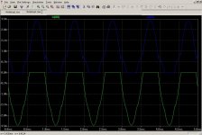
Here is the circuit in LTspice - same as in post 7.
The collector currents are not a pretty picture, as shown. The static bias collector current is about 1A for each output transistor, i.e. each transistor dissipates 32W by just being powered on. This probably means that the heatsink has to be little bigger than might otherwise be the case, but I haven't done the math. As my textbooks used to say, that is left as an exercise for the reader.

The less than optimal biasing is the downside of this circuit, and the price to be paid for easy setup.
Attachments

- Status
- Not open for further replies.
- Home
- Amplifiers
- Solid State
- 45W@8R 70W@4R CLASS B SO LOW DISTORTION.