Changes made.
Before I get into the results let me put this question out to the group:
Just how low of a ripple can you get from a direct heated 45 with AC on the filament? (At speaker)
Maybe I’m chasing unicorns here?
EML website says anything under 1mV is a “fine piece of work”. (I was under half a millivolt)
OK onto the results:
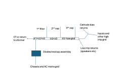
Moved the ground wires to run from center tap to 1st cap to 2nd cap then to the star.
Ripple measured at the speaker:
Before: 0.48mV
Now: 0.49mV
Worse, certainly not better.
Also
60Hz very slight decreased
120Hz very slight increased
Makes no sense.
Only thing I can come up with is the ground wire between the first and second cap now crosses the high ripple wire between the rectifier and choke. (They are at 90° and separated vertically about an inch).
I mean the physical separation I lost has to count for something doesn’t it? That doesn’t seem to get mentioned much in any grounding discussion.
Think I am going to try something in between:
Center tap to first cap then to star. Second cap to the star. That will avoid crossing the rectifier to choke wire.
Good news is, it’s still less than half a millivolt ripple. 101 DB efficient speakers and I still don’t hear any hum unless my ear is shoved into the driver.
Before I get into the results let me put this question out to the group:
Just how low of a ripple can you get from a direct heated 45 with AC on the filament? (At speaker)
Maybe I’m chasing unicorns here?
EML website says anything under 1mV is a “fine piece of work”. (I was under half a millivolt)
OK onto the results:
Moved the ground wires to run from center tap to 1st cap to 2nd cap then to the star.
Ripple measured at the speaker:
Before: 0.48mV
Now: 0.49mV
Worse, certainly not better.
Also
60Hz very slight decreased
120Hz very slight increased
Makes no sense.
Only thing I can come up with is the ground wire between the first and second cap now crosses the high ripple wire between the rectifier and choke. (They are at 90° and separated vertically about an inch).
I mean the physical separation I lost has to count for something doesn’t it? That doesn’t seem to get mentioned much in any grounding discussion.
Think I am going to try something in between:
Center tap to first cap then to star. Second cap to the star. That will avoid crossing the rectifier to choke wire.
Good news is, it’s still less than half a millivolt ripple. 101 DB efficient speakers and I still don’t hear any hum unless my ear is shoved into the driver.
Last edited:
I guess I don't understand what you are chasing here. You measure 1/2 of what a respected tube manufacturer states is excellent. Your system, with exceptionally sensitive speakers, is plenty quiet to your ears. You are AC heating your tubes!
And further reduction in noise seems like it would be lost in the AC.
And further reduction in noise seems like it would be lost in the AC.

If the amplifier is in "silent mode" (shorted input, no signal within an amplifier), high ripple current occurs only between rectifier and first cap positive, and first cap negative to CT.Only thing I can come up with is the ground wire between the first and second cap now crosses the high ripple wire between the rectifier and choke. (They are at 90° and separated vertically about an inch).
These are -in my schematic simulation- 330mA spikes (if the steady current of load is 90mA).
Via the choke only the second cap charging pulses moving, about 4-5mA (mostly sinusoid, than first cap charging pulses).
So, as we repeated many times, the most critique chain is secondary-rectifier-first capacitor-CT.
BTW why not place choke "output" wire on the other side of second capacitor?
Started simple. Did not renew the entire grounding, just rearranged PT, C1, Choke ground wires.
While not ideal, I’m wondering if the grounding is NOT the limiting factor. How much can you get from a basic CLC filter along with AC filaments?

Red circle is where ground now crosses rectifier output. 1 inch vertical separation. Possible this is the cause of the very slight increase in 120 Hz?
While not ideal, I’m wondering if the grounding is NOT the limiting factor. How much can you get from a basic CLC filter along with AC filaments?
Could you please post an 'after' pic?
Red circle is where ground now crosses rectifier output. 1 inch vertical separation. Possible this is the cause of the very slight increase in 120 Hz?
Last edited:
The only reason those grounds can be noisy is by isolating them from the actual ground. There can't be noise in a zero ohm connection to "ground". And seriously stop and think a second, how much resistance is there in a couple of inches of solid 18ga copper wire (0.001 ohms?) and is that really going to have any impact on reducing or isolating a "noisy ground"?Rob7,
I use the scheme as shown the idea is to distance the noisy from the quiet gnds. Again, this is my way that maybe total BS to someone else.🤣
I have 104db horns and there is no audible buzz or noise of any kind.
ir1= ripple current from cap 1 etc.
You can see where the high ripple areas are located. The ir2+ir2+ir3 being the worst sum of the major ripple currents from filter caps.
I do agree the RCA "ground" is actually the return signal path and should not be brought all the way back to the main star ground point individually but should be connected to ta local ground at the input tube used for the cathode/grid leak resistor. Nothing good will come from having the return signal path being taken all the way back to the power supply ground and then back to the tube cathode/grid leak/volume pot via another ground wire in parallel to it.
Rob,
Use grounding scheme as you sketched in #25 post!
Using such extremely long wires -for example- from #45 cathode resistor AND decoupling capacitor negative to the "grounding point" is unreasonable.
Why not connected its together in capacitor negative?
Always use as short wirings as possible.
Use grounding scheme as you sketched in #25 post!
Using such extremely long wires -for example- from #45 cathode resistor AND decoupling capacitor negative to the "grounding point" is unreasonable.
Why not connected its together in capacitor negative?
Always use as short wirings as possible.
Last edited:
Wanted to start with the basics and one change at a time.Use grounding scheme as you sketched in #25 post!
I am building the second monoblock now. Will ground as shown in post 25. (If nothing else because it will be easier!) If it is indeed quieter, I will go back and redo the first one the same.
Again, maybe my very basic CLC filter is the limiting factor here?
Also, a rather small output transformer isn’t helping with the filtering at speaker out. Maybe need to measure the ripple at B+ and B+2 to see how it compares to your modeling.
Last edited:
Makes sense. Thanks. Will do after Im done fiddling with the first capacitor grounding. Don’t want to add another variable yet.I do agree the RCA "ground" is actually the return signal path and should not be brought all the way back to the main star ground point individually but should be connected to ta local ground at the input tube used for the cathode/grid leak resistor.
Rob7,Started simple. Did not renew the entire grounding, just rearranged PT, C1, Choke ground wires.
While not ideal, I’m wondering if the grounding is NOT the limiting factor. How much can you get from a basic CLC filter along with AC filaments?
Red circle is where ground now crosses rectifier output. 1 inch vertical separation. Possible this is the cause of the very slight increase in 120 Hz?
that does not look like an improvement IMHO, but then again it may not matter in the end. Does it buzz?
You asked about 'what's best' and this is what we are trying to suggest. One of the thing about diyaudio, it is a endless journey of optimization, tests and discoveries. I have amended my scheme, I had forgotten my low imp return connection. I find that to be important.
Attachments
I fully agree. And use solid 12ga for the caps like I mentioned before, not 14ga please! 😉Rob,
Use grounding scheme as you sketched in #25 post!

Thanks! That’s exactly why I started this thread. Not because a specific hum or buzz—as built the amp is relatively quiet. Can hear zero hum at half a meter.You asked about 'what's best' and this is what we are trying to suggest.
101dB speakers. Have to put my ear into the driver to hear it. Certainly cannot hear anything from the seated position. I wanted critique of my work and suggestions so I can learn.
Last edited:
Tag strip as star mounted to rectifier socket screw (drawn in green in post 25)?
Use ground bus EXACTLY isolated from any metal part!
I usually use ceramic (see V-Cap mounting) or micanol (brown tag in the middle) isolators.

The hum blocker (#26 post) will connect the ground bus (grounding point) to safety ground/metal cover sheet.
I usually use ceramic (see V-Cap mounting) or micanol (brown tag in the middle) isolators.
The hum blocker (#26 post) will connect the ground bus (grounding point) to safety ground/metal cover sheet.
I don't see why you should hear anything at all, ever. So there is room for improvement!Thanks! That’s exactly why I started this thread. Not because a specific hum or buzz—as built the amp is relatively quiet. Can hear zero hum at half a meter.
101dB speakers. Have to put my ear into the driver to hear it. Certainly cannot hear anything from the seated position. I wanted critique of my work and suggestions so I can learn.
😉

Yes, but…is the grounding system the limiting factor in this case? To see any benefit, might I need a more robust power supply design? just don’t want misdirected energies if there is another even weaker link in the system.there is room for improvement!
… doesn’t mean I don’t want the grounding done right! Just difficult to hear or measure improvements to grounding if there is a weaker link elsewhere.
6A3s set the bar very high at 0.1mV at speaker! (That’s my goal, but wonder if that even can be accomplished with AC filament?) i’d be ecstatic if I could get into the .3 mV range. Maybe not possible with current power supply. But I’m gonna keep trying. Good learning for my next build where I plan a more robust power transformer and PS.
6A3s set the bar very high at 0.1mV at speaker! (That’s my goal, but wonder if that even can be accomplished with AC filament?) i’d be ecstatic if I could get into the .3 mV range. Maybe not possible with current power supply. But I’m gonna keep trying. Good learning for my next build where I plan a more robust power transformer and PS.
Last edited:
Second mono block is underway. Will do this. Thanks!
- Home
- Amplifiers
- Tubes / Valves
- 45 tube amp grounding critique (with photo)