It is 3:44 AM for me.
I will not read through all the responses, Instead . . .
Secondary 1 to rectifier plate 1
Secondary 2 to rectifier plate 2
Cathode to first capacitor +
Secondary Center tap to first capacitor - (wire # 1)
First capacitor + to either a Resistor, or a Choke; from the other end of that resistor or choke, to the second capacitor +.
First capacitor - to the second capacitor - (wire #2).
Second capacitor - to the central ground (wire # 3).
Do not connect the first capacitor negative directly to the center ground. That will include the transient, high frequency harmonics content of the rectifier and first capacitor directly to the central ground.
By the time the B+ has gone through the resistor or choke, to the second capacitor, the transient high frequency harmonic content has been filtered somewhat.
Controlling the first hum and transient loop, and making it Local, is the key.
If that does not make it clear, sorry.
It works for me (less than 100uV in my amplifier outputs (Less than 100 Micro Volts).
All the other methods may be equaly valid, or not equally valid; I list what works for me.
Thank you! I finally got it.It is 3:44 AM for me.
Thanks all for your patience…Especially euro21 and 6A3sUMMER who stuck with me from the beginning. With a special shout out to Stephe. Her link with the detailed explanation and diagrams was the missing piece of the puzzle that helped me visualize this.
Photos and measurements to come.
I am explaining EXACTLY why I don't like your way of doing it but I am opened to the possibility I maybe totally wrong. Again, it is my belief that the ripple current from the first cap after the rectifier is the most severe source of noise and that current should be sent straight back to the CT and not propagated out to the start gnd where it infects the cathode bypass gnds and the input gnd. My grounding arrangement is always very short and done a little differently but the idea remains the same. I use as low an ESR cap as I can find as first cap, too.If that is "bad mojo", why are all my amps built like this quiet? But doesn't shock me, anything I post of this forum is TRASHED, not sure why I even bother replying here anymore.
Note in this article, they don't show in their star ground examples the cap grounds being all daisy chained across the amp before going to the star ground point. https://www.valvewizard.co.uk/Grounding.pdf
I would be VERY interested in knowing why you don't agree with what seems like a very straight forward concept.
Last edited:
These are only simulations of long wirings in Rob's amplifier.
More worst, than in practice, but necessary to exaggerate to demonstrate possible differences.
The load is 20Hz 0...180mA current load (90mA biased A class).
The displayed signal is the amplifier part "ground" bus.
The first is the commonly used: CT to first cap negative, wiring to second cap negative, which is tied to grounding point. Each load "negative" tied to second cap negative. Shortest loop: C2 is the main energy storage device -for short load impulses- so the main current loop is between B++ (second capacitor positive) to PSU "negative" (second capacitor negative).
The second is Stephe's suggestion: CT to grounding point. First cap negative to grounding point. Second cap negative to grounding point. Each load "negative" tied to second cap negative (shortest loop).

Exactly better.
The AC connector safety ground point must to tied with very short wire to metal part of chassis. It's not part of grounding scheme.
If the amplifier working (be sure, that each "ground" -channel 0 points, capacitors, connectors etc.- independent from metal sheet), the hum (exist, or not, disturbing, or not) decides, which type hum blocker needs (if needs): 10-100R to "house ground", R//C, or diodes too.
samples:
Rob7
Yep. To be compatible with your arrangement, I would use some solid 12ga electrical wire bend it into an L and make a uninterrupted connection between the 3 motorrun caps. Section off the area of the insulation where you need to solder to the caps. At some point have a connection between that and the blue buss.
Yep. To be compatible with your arrangement, I would use some solid 12ga electrical wire bend it into an L and make a uninterrupted connection between the 3 motorrun caps. Section off the area of the insulation where you need to solder to the caps. At some point have a connection between that and the blue buss.
I never connected the input RCA negative to the ground bus.
It's signal wire, must to connect the first "local ground" point (for example cathode resistor negative point, or potentiometer "negative").
The channel negative "0" wire (from the largest current stage "local ground" point -for example power tube cathode resistor negative) tied to PSU negative (or to ground bus).
euro21,
I agree, my RCA input connectors ground is insulated from the chassis.
Instead, it ties to the bottom of the volume control pot, and also to the bottom of the input tube's cathode self bias resistor (and that self bias resistor is either cap bypassed, or not cap bypassed).
My CD player is essentially floating, it uses a 2 wire mains plug. The CD player RCA connector output, to the RCA cable, through the amplifier input, is effectively grounded at the volume control and bias resistor.
From there the self bias resistor goes to the central ground point of the amplifier.
That input ground loop is as short as possible, and the self bias resistor to central ground is longer.
Works for me.
Stephe,
You have lots of fans.
I wish I had the time to look at all your videos and posts.
Nobody is perfect, especially me. I make lots of mistakes. It becomes the "New" first impression people have of me.
I second that. Steph was one of the people that inspired me to build some tube gear.
Thanks all—this is coming together in my head. Next question.
In last photo (post 25)where should the star ground to the chassis?
Many articles advocate for the ground to chassis be at the input, which seems counter to what everyone is saying here. Possibly I am just misunderstanding…again!
In last photo (post 25)where should the star ground to the chassis?
Many articles advocate for the ground to chassis be at the input, which seems counter to what everyone is saying here. Possibly I am just misunderstanding…again!
Last edited:
Looks like you are trying to go with a bus bar grounding system instead of the star ground you originally wired up.
Try considering that the SIGNAL ground is different from the CHASSIS/EARTH ground. if I were doing it, I would run a 14AWG wire between the two caps and bring each individual wire to that wire. I keep all the grounds from each stage together. The transformer center-tap gets hooked to C1. There is NO need to tie the SIGNAL ground to the chassis but I usually do through that hum breaker mentioned earlier.
Try considering that the SIGNAL ground is different from the CHASSIS/EARTH ground. if I were doing it, I would run a 14AWG wire between the two caps and bring each individual wire to that wire. I keep all the grounds from each stage together. The transformer center-tap gets hooked to C1. There is NO need to tie the SIGNAL ground to the chassis but I usually do through that hum breaker mentioned earlier.
That blue line was supposed to represent a tag strip. Was considering moving the Star ground to Central location. But you and another member have now mentioned putting heavy gauge wire between the caps. That would make for a good bus. Interesting thought.bus bar grounding system instead of the star ground
The location of the tag strip makes no difference as long as the strip is isolated from the chassis. If I was doing your amp, I would experiment using a test lead for the quietest return point.
"Grounds" are the source of more confusion than just about anything else in audio construction (and often in system installations too - I've seen plenty of professionals get things wrong). We tend to fall back onto established cookbook methods because they work at least well enough, and because there are no ideal, perfect solutions - all methods are imperfect.
Let me suggest that to develope a working mental model about how to choose an optimum path we do two things. First would be to abstract our thoughts one step, from actual parts to a schematic. I suggest this because the interesting parts are there, but without the distractions.
Second would be to stop using the conventional "ground" symbols in the signal and power supply paths in schematics. This convention causes endless confusion because it's false. Instead we should draw and think about things as euro21 has drawn them, with actual (or estimated) impedances in place. This encourages us to think in currents when appropriate, and not always in voltages, and without imaginary perfect "grounds" which don't exist.
There are no perfect solutions for single-ended circuits, and star "grounds" are only a series of loops. Also we must remember that a stereo amplifier's channels are common-grounded at the source - another loop. Lotsa compromizes.
All good fortune,
Chris
Rob7,
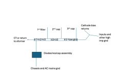
I use the scheme as shown the idea is to distance the noisy from the quiet gnds. Again, this is my way that maybe total BS to someone else.🤣
I have 104db horns and there is no audible buzz or noise of any kind.
ir1= ripple current from cap 1 etc.
You can see where the high ripple areas are located. The ir2+ir2+ir3 being the worst sum of the major ripple currents from filter caps.
Attachments
Please don't say that, you are one of those who answer the most, you are certainly one of the people who gives the most complete and technical answers.I make lots of mistakes. It becomes the "New" first impression people have of me.
Be thanked for it.
That`s just how i ground my amps.👍Rob7,
I use the scheme as shown the idea is to distance the noisy from the quiet gnds. Again, this is my way that maybe total BS to someone else.🤣
I have 104db horns and there is no audible buzz or noise of any kind.
ir1= ripple current from cap 1 etc.
You can see where the high ripple areas are located. The ir2+ir2+ir3 being the worst sum of the major ripple currents from filter caps.
- Home
- Amplifiers
- Tubes / Valves
- 45 tube amp grounding critique (with photo)