If you look at the curves I posted above, the 03N100D will set the VDS of the below FET at double the voltage compared the DN2540. That’s it about 3V versus 1.5V for 30mA drain current. Now, if you go to the DN2540 and check the model capacitances versus VDS (Crss in particular), you will notice they decrease at higher VDS. Ideally +25V, but you can’t achieve that unless you add some battery bias (you can if you want) on the top device.
I tried a comparison between the battery bias and a IXT01N100D, and frankly found just a small improvement in HF. With the 01N100D you can do well above 1Mhz BW, which is much more than you need already.
Ale
I tried a comparison between the battery bias and a IXT01N100D, and frankly found just a small improvement in HF. With the 01N100D you can do well above 1Mhz BW, which is much more than you need already.
Ale
Ale,
With resistor bias for driver tube, gyrator capacitor (from anode to gate of the lower FET) should be at least 0.47uF. Because of LF.
Check it.
With resistor bias for driver tube, gyrator capacitor (from anode to gate of the lower FET) should be at least 0.47uF. Because of LF.
Check it.
If you look at the curves I posted above, the 03N100D will set the VDS of the below FET at double the voltage compared the DN2540.
Jut wanted to go ahead and order some parts. I can't find anything called "03N100D" or "IXTP03N100D". Mouser has IXTP3N100P or IXTP3N100D2. Which one is it?
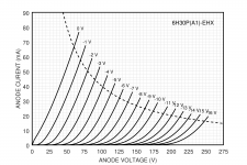
Ok, parts start coming in. I put the 6H30P (Electroharmonix) tubes in my brand-new tube tracer and got the attached curves. Something is not right going from the -10V to -11V trace. This is the same for both triode units, and also with a second 6H30P. I don't think I'd push the signal to -10V very often, but still... does anyone have an idea what's going on with these tubes?
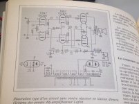
Find this directly coupled " Lafon " 45 amplifier
in my old paper " L'Audiophile" collection 🙂
in my old paper " L'Audiophile" collection 🙂
Attachments

Find this directly coupled " Lafon " 45 amplifier
in my old paper " L'Audiophile" collection 🙂
Nice! Can you scan the full article? Yes, I do understand some french if I really have to 😀
Hi Soundhappy
Push-Pull 45 is a nice idea. These days though, 45‘s are getting more expensive to source. Pity that.
The Cascaded 6sn7 brings almost too much gain for the little 45 tube. Indeed, it would be a lot for 2a3 as well. Also, output impedance is really still high on the 45 grid. Last part that I don‘t like with these designs is that the whole thing works like a house of cards - it assumes all valves/tubes are in like-new condition running like in the specs sheet.
Also, that variable 2.5K Ohm 50 watt cathode resistor... Pretty big. And no cathode by-pass cap from point G to ground? I have a hunch that bass response might suffer. Did you ever hear this amplifier?
Ian
Last edited:
That pretty much summarises my thoughts when I looked at the schematic. It would still be interesting to read the text. There are sometimes some nice ideas hidden in those circuit descriptions that are not obvious just from looking at the schematic alone.
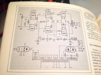
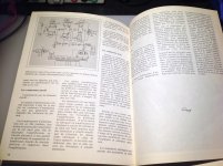
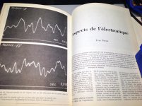
45 amp " Lafon " amplifier schematic was inculded into article
"Aspects of electronics " but not precise informations, bandwith frequence response , constructions details etc.
"Aspects of electronics " but not precise informations, bandwith frequence response , constructions details etc.
Attachments
45 amp " Lafon " amplifier schematic was inculded into article
"Aspects of electronics " but not precise informations, bandwith frequence response , constructions details etc.
Just found that :
http://www.lechauffeurdecathodes.fr/tlr224.pdf
Partssss.... Muuaaahahahaaaaaa!!!
Hey mbrennwa - did you ever finish this amplifier?
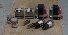
I believe I see a pair of chokes and two pairs of transformers in your pic, how is the second pair of transformers used?
I have a 45 parafeed speaker amplifier that uses Sowter 8983 OPT, the 45 are loaded by a CCS rather than a choke however, stages are RC coupled. I am considering picking up a pair of 8985 chokes to replace the CCS loads and direct-coupling the stages, very little in the original circuit would need to change actually.
Also, I'm curious what turns ratio you used on your 10K headphone transformers. Do they have multiple taps or single? Thank you 🙂
I have not yet built this. Had to focus on things that I needed more than a headphone amp. But it's still in the queue!
The photo shows the output transformers and some transformer volume controls I used with my DDDAC.
Please report back how your mod to DC coupled goes.
The photo shows the output transformers and some transformer volume controls I used with my DDDAC.
Please report back how your mod to DC coupled goes.
- Home
- Amplifiers
- Tubes / Valves
- 45 amp build direct coupled