@MikeHunt79:
The limiting value/component is the driver chip (TP2350B) which is designed to drive MOSFETs with a maximum Qg of "just" 120nC.
If you wanna use 8 output trannies per channel, be sure the total Qg is not very much above the 120nC (... divided by 4 makes 30nC max. for each MOSFET) otherwise you might fry the driver chip (a "large" heatsink is highly recommended in this case - i.e. see picture of 'theAnonymous1').
It's more likely to find MOSFETs with a small Qg having only small Vds ratings. So it's possible to drive 2 ohm loads with the "disadvantage" of a lower power supply value, hence a lower maximum output power.
Maybe you can find the "magical" MOSFET with a very low Qg, high Vds, low Ron, ... 😉
Besides finding the right MOSFET you have to change the over-current limiting resistor(s) to allow for higher currents to the 2 ohm load.
The board itself, without any modifications, isn't really prepared to handle such a high current application. However I recommend in this case to 'strengthen' the tracks by using litz wire soldered on the high current paths just above the corresponding tracks.
 Actually I wouldn't spend to much time in designing a new PCB because Tripath went bankrupt and was bought by Cirrus Logic for just 3.25 million US-$ (if I'm not mistaken - quite a bargain though). As long as nobody knows that Cirrus is continuing to produce Tripath chips I wouldn't continue with any (re)designs/modifications based on (former) Tripath chips. Even the homepage of Tripath is shut down. So, do yourself a favour and don't stick with Tripath chip(s). My feeling is that these chips are dead and only available from distributors as long as their stock lasts.
The limiting value/component is the driver chip (TP2350B) which is designed to drive MOSFETs with a maximum Qg of "just" 120nC.
If you wanna use 8 output trannies per channel, be sure the total Qg is not very much above the 120nC (... divided by 4 makes 30nC max. for each MOSFET) otherwise you might fry the driver chip (a "large" heatsink is highly recommended in this case - i.e. see picture of 'theAnonymous1').
It's more likely to find MOSFETs with a small Qg having only small Vds ratings. So it's possible to drive 2 ohm loads with the "disadvantage" of a lower power supply value, hence a lower maximum output power.
Maybe you can find the "magical" MOSFET with a very low Qg, high Vds, low Ron, ... 😉
Besides finding the right MOSFET you have to change the over-current limiting resistor(s) to allow for higher currents to the 2 ohm load.
The board itself, without any modifications, isn't really prepared to handle such a high current application. However I recommend in this case to 'strengthen' the tracks by using litz wire soldered on the high current paths just above the corresponding tracks.
Actually I wouldn't spend to much time in designing a new PCB because Tripath went bankrupt and was bought by Cirrus Logic for just 3.25 million US-$ (if I'm not mistaken - quite a bargain though). As long as nobody knows that Cirrus is continuing to produce Tripath chips I wouldn't continue with any (re)designs/modifications based on (former) Tripath chips. Even the homepage of Tripath is shut down. So, do yourself a favour and don't stick with Tripath chip(s). My feeling is that these chips are dead and only available from distributors as long as their stock lasts. You could try the FDP3651U 80A FETs I put in my RB-TDA2500 board. They are only rated at 100v so you would have to use a lower supply voltage, but they should be able handle a 2 ohm load with no problems.
The tracks of the AMP2 are puny compared to the RB-TDA2500 so I would be careful trying to squeeze too much current out of it. You would at least need to bulk up the high current paths like Corax suggested.
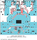
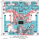
EDIT: If you take a look at the data sheet for the TA0102A there is a "TEST/APPLICATION CIRCUIT" on page 5 that shows the high current paths. I know this is a diffferent IC, but it gives you a general idea of where the current is flowing.
http://www.ortodoxism.ro/datasheets/Tripath/mXyzxwxq.pdf
The tracks of the AMP2 are puny compared to the RB-TDA2500 so I would be careful trying to squeeze too much current out of it. You would at least need to bulk up the high current paths like Corax suggested.
EDIT: If you take a look at the data sheet for the TA0102A there is a "TEST/APPLICATION CIRCUIT" on page 5 that shows the high current paths. I know this is a diffferent IC, but it gives you a general idea of where the current is flowing.
http://www.ortodoxism.ro/datasheets/Tripath/mXyzxwxq.pdf
Anyone have a picture of the PCB layout? Any way to reverse engineer it so I could try to add 4 more drivers to it?
Hi
Why do you need to add 4 more fets?!? You can bridge it...if that is not enough power then find some other amp
Why do you need to add 4 more fets?!? You can bridge it...if that is not enough power then find some other amp
The potential of these amps seem like the first thing to break in your home stereo system would be the speakers or your electrical breaker in your home!  I love it!
Remember there is time to enjoy music, and there are times where you just want your ears bleeding
I love it!Remember there is time to enjoy music, and there are times where you just want your ears bleeding
Hi
I know, way ahead of you 😀, in my case I want my speakers to scream 😀
Remember there is time to enjoy music, and there are times where you just want your ears bleeding
I know, way ahead of you 😀, in my case I want my speakers to scream 😀
Hi
Tomorrow will come power test, smps is now working ok, waveforms are great, now all I need to do is solder power cabels to PCB and test it. Amp won't be connected just jet.

Tomorrow will come power test, smps is now working ok, waveforms are great, now all I need to do is solder power cabels to PCB and test it. Amp won't be connected just jet.
Hi
Good news, after some problems... I was able to get 273w on bench with 11.59v @ CT and 94.7 on output...
Then in car, first with 50Hz tone, 11.0v input of smps, which is 0.5m away from CT, connected with 20mm^2, output of smps should be 93v, amp was just before clip I think, so about 270w sinewave on 240w rated sub 🙄
Then with car on, output voltage was pretty much dead solid at 126v, volume was pretty high and I was. At that point I stoped because I was afraid I would burn speaker, or break panels of my car or something like that...
There was ~7C in car, so was smps and amp, no heat what so ever, just output inductors of both channel and chip (driver), and they had about say 20C
Now I think is time to finish case, and make other circuits for it...I want to see the power of bridge 😀
Good news, after some problems... I was able to get 273w on bench with 11.59v @ CT and 94.7 on output...
Then in car, first with 50Hz tone, 11.0v input of smps, which is 0.5m away from CT, connected with 20mm^2, output of smps should be 93v, amp was just before clip I think, so about 270w sinewave on 240w rated sub 🙄
Then with car on, output voltage was pretty much dead solid at 126v, volume was pretty high and I was
. At that point I stoped because I was afraid I would burn speaker, or break panels of my car or something like that...There was ~7C in car, so was smps and amp, no heat what so ever, just output inductors of both channel and chip (driver), and they had about say 20C
Now I think is time to finish case, and make other circuits for it...I want to see the power of bridge 😀
Hey, nice switchmode supply! What driver did you use?
I think Jan can still supply the older PCB of AMP2 for those who are interested.... Want me to ask him?
I think Jan can still supply the older PCB of AMP2 for those who are interested.... Want me to ask him?
- Status
- Not open for further replies.
- Home
- Amplifiers
- Class D
- 41Hz AMP2 upgrade?