I've been reading on how to get more power out of the 41Hz AMP2. As they say you can get alot more power by doing a few things, however you may need to add more FETs to help with heat. They also claim that "there is room on the board for this". Umm, i could only find a few select pictures of the Tru amp and they do not have places to add more FETs. Anyone have a photo of the AMP2 board so I may conferm that this upgrade is possible?
Thank-you
Thank-you
Hi
I think that was for older versions of AMP2, which could have up to 8 to-220 fets on, now you have 4 of to-247, big ones.As far as I know you only have to change current limit, I used 12k resistors to set current to 22A
I think that was for older versions of AMP2, which could have up to 8 to-220 fets on, now you have 4 of to-247, big ones.As far as I know you only have to change current limit, I used 12k resistors to set current to 22A
luka said:Hi
I think that was for older versions of AMP2, which could have up to 8 to-220 fets on, now you have 4 of to-247, big ones.As far as I know you only have to change current limit, I used 12k resistors to set current to 22A
Really, thats good to hear. What are you running on yours? I can assume a +-60VDC rail, but you running bridged? what kind or load do you have. What the the C/W rating on your heat sink?
Hi
Jup +/-60, not bridge yet, not tested at full power, still building supply for it. I will drive probably 4R, but 8R wouldn't hurt
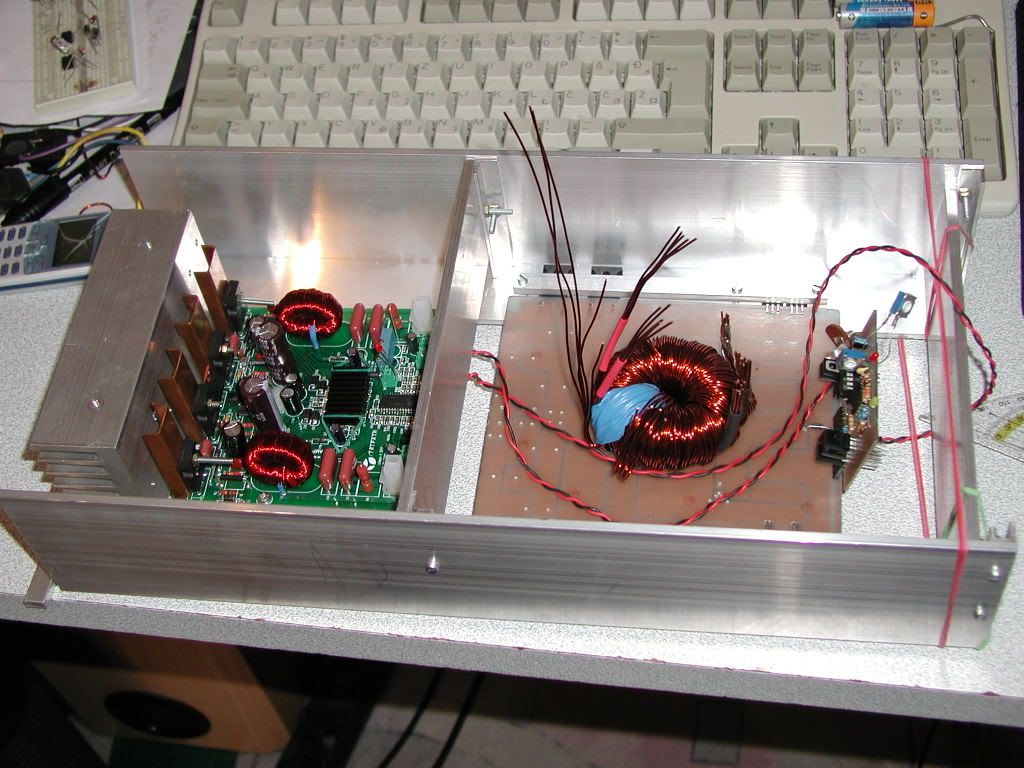
I have no idea C/W rating does it have. It is 66mm x 135mm x 40mm(10mm solid base). It will be overkill, since I will use fan to cool chipset + inductors and heatsink all at the same time. I will use it in car, where can get damn hot, and I don't want to destroy the amp
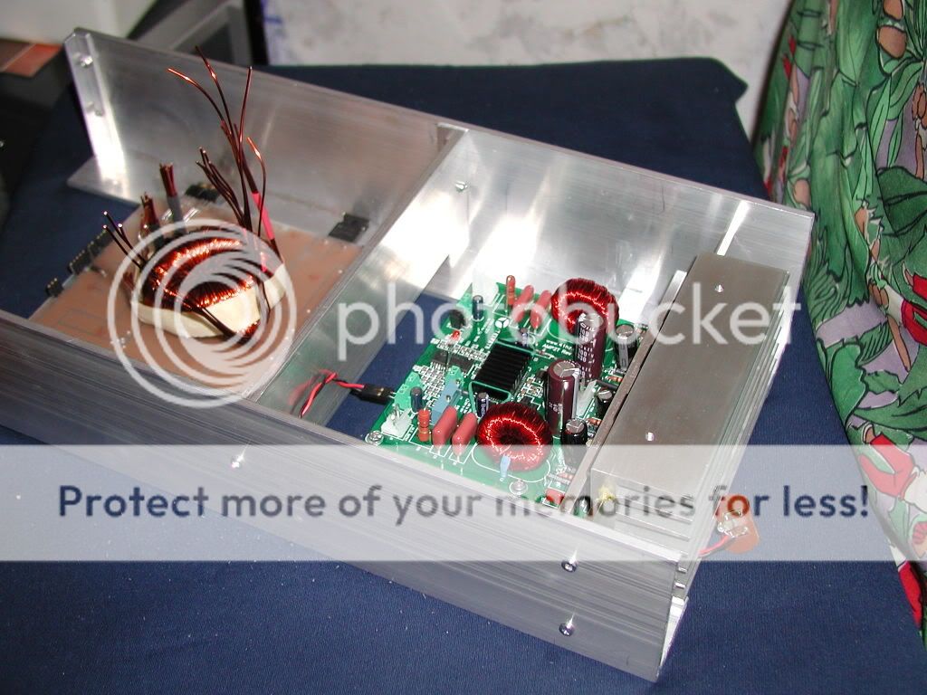
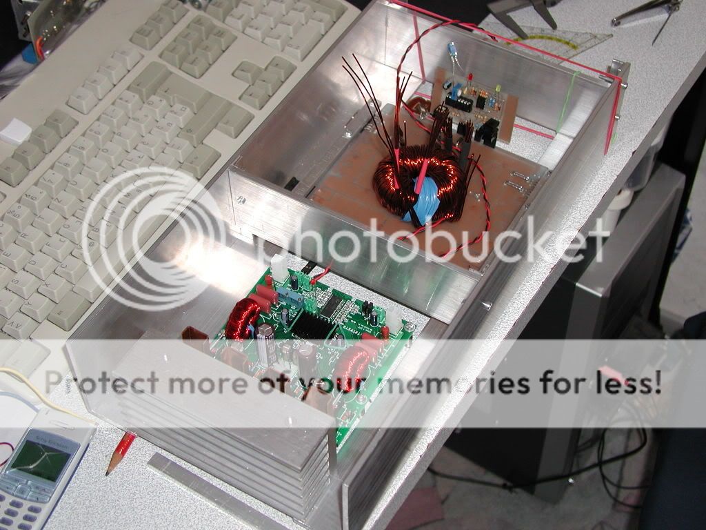
Under construction, so not much to see
Jup +/-60, not bridge yet, not tested at full power, still building supply for it. I will drive probably 4R, but 8R wouldn't hurt
I have no idea C/W rating does it have. It is 66mm x 135mm x 40mm(10mm solid base). It will be overkill, since I will use fan to cool chipset + inductors and heatsink all at the same time. I will use it in car, where can get damn hot, and I don't want to destroy the amp
Under construction, so not much to see
Hi
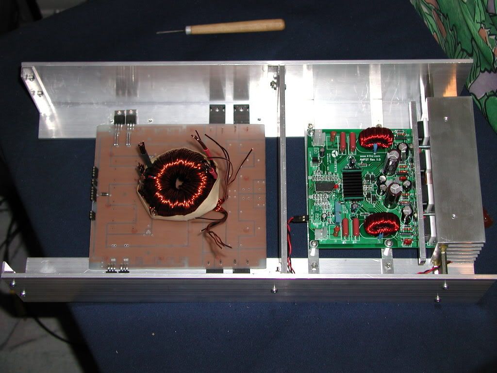
Looking good? Well thanks, didn't think building is step by step, with no plan, I would even get it even to stay together, but it is strong at least something. All now depends on push pull, today I will pick up my new core for it.
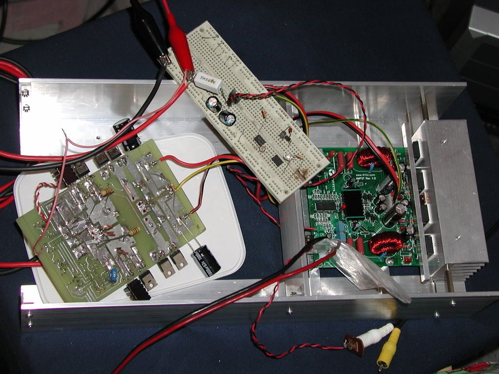
That breadboard is legacy from my father, he didn't really say what happened, I guess one day got really hot 😀
You know how those breadboards are, only low current, not that good connections + it is older then I am, but for some small and quick test is ok
Looking good? Well thanks, didn't think building is step by step, with no plan, I would even get it even to stay together, but it is strong at least something. All now depends on push pull, today I will pick up my new core for it.
That breadboard is legacy from my father, he didn't really say what happened, I guess one day got really hot 😀
You know how those breadboards are, only low current, not that good connections + it is older then I am, but for some small and quick test is ok
@MotoMan & @luka,
Both PCB versions of the AMP2 are designed for TO247 devices.
The only difference is, as you already mentioned luka, the number of TO247 devices.
😀 The "older" version was a layout of Jan himself - with 4 trannies for each channel (a total of 8 though) - designed (according to Jan himself) to bridge two channels for >1000W output power 😀 .
The "newer" version with just 2 trannies for each channel (total of 4) is the original Tripath evaluation board design - the same as shown in your pictures luka.
And I'm pleased to say it's a nice work so far.
Let us know when your SMPS is done and running (under full load).
It's possible to streeeeeeeeeeetch some TO-220 FETs into place. Below is a pic of my eval board with FDP42AN15A0 FETs. These are the same FETs used on the UCD400. They have much better specs than the STW34NB20.
An externally hosted image should be here but it was not working when we last tested it.
@theAnonymous1:
Well, I wouldn't state that the Fairchild FDP42AN15A0 has much better specs - I would just call it slightly better. 😀
OK, the total gate charge is doubled and the RDS(on) is a little worst if I compare it with the Fairchild, but this is most likely due to the fact that the ST MOSFET has a higher VDSS (of 200V instead of "just" 150V). This is generally an effect that always goes along with MOSFETs. The lower the VDSS the better are usually the values for i.e. Qg(tot), RDS(on), ... 😉
Besides - on your nice picture you "bolted" the output trannies via a massive metal bar on the heatsink. In my amp I just made threads into the bar and mounted the srews from the outside. This way I got rid of fiddling around with a screwdriver inside the case. Very often the screwheads are blocked by bulk capacitors (so don't remind me about the AMP5 from Jan - nevertheless a good amp though).
Well, I wouldn't state that the Fairchild FDP42AN15A0 has much better specs - I would just call it slightly better. 😀
OK, the total gate charge is doubled and the RDS(on) is a little worst if I compare it with the Fairchild, but this is most likely due to the fact that the ST MOSFET has a higher VDSS (of 200V instead of "just" 150V). This is generally an effect that always goes along with MOSFETs. The lower the VDSS the better are usually the values for i.e. Qg(tot), RDS(on), ... 😉
Besides - on your nice picture you "bolted" the output trannies via a massive metal bar on the heatsink. In my amp I just made threads into the bar and mounted the srews from the outside. This way I got rid of fiddling around with a screwdriver inside the case. Very often the screwheads are blocked by bulk capacitors (so don't remind me about the AMP5 from Jan
- nevertheless a good amp though).Corax said:Well, I wouldn't state that the Fairchild FDP42AN15A0 has much better specs - I would just call it slightly better. 😀
Shhhhh...... their magical FETs (let me have my moment).

I don't need a 200v device when it will only ever see ~120v.
Yes, the screws for the clamps are a bit of a pain due to the supply caps, but they were already there so that's what I used for now. Maybe I will put some threaded rod into the heatsink and use a nut instead.
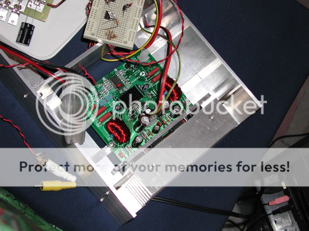
ashok said:Is the metal slug under the main chip (under the small heatsink )soldered to the pcb ?
Yes, but mine is a genuine eval board, so I didn't have to worry about that hassle myself. The IC still gets too hot for my taste, so I added the small heatsink on top.
I have the original board with space for 4 TO247 devices per channel. I haven't yet got round to assembling it ( after a couple of years !) The two main things that stalled me were the issue of soldering the metal lug and the need to change parts and power transistors if I used 4 per channel .
What are the best devices that are currently available for use in a 4 per channel configuration. Jan mentioned some changes to resistor values etc. Has anyone done this and what were they ?
Thanks.
What are the best devices that are currently available for use in a 4 per channel configuration. Jan mentioned some changes to resistor values etc. Has anyone done this and what were they ?
Thanks.
ashok said:Is the metal slug under the main chip (under the small heatsink )soldered to the pcb ?
I have soldered it myself and as far as I can see it works very well
Corax
First of all thanks.
Jup I will update you as soon as things move a bit
Hi ashok
Jup I have, as far as I can see, my kit, had everything ok, I had to change only overcurrent resistors with 12k smds
@ashok:
I found a forum thread where Jan mentioned what to do for a high power version with 4 trannies per channel. Here's the excerpt:
I couldn't do all the changes myself because of the original Tripath eval board (the later PCB version of AMP2) with only 2 trannies per channel. Nevertheless I made the +/-60V version to get a little more power on 8 ohm speakers with a conventional power supply (toroid - rectifier - bulk caps) 🙂
I found a forum thread where Jan mentioned what to do for a high power version with 4 trannies per channel. Here's the excerpt:
Here is a summary of component changes that could be made for a "Very High Power" solution compared to the standard solution for the AMP2 board
- Four more MOSFETs, preferably a type with low gate charge
- Four more gate resistors and diodes. The resistor should be half the value of the 4 MOSFET version, probably 10 ohm but this is dependent on what MOSFETs are used.
- Six more anti ringing caps (220 pf) with their associated 16 ohm resistors for the MOSFETS
- Larger power caps. Four 470 uF, 100V rail to ground, two 150 uF 160V rail to rail
- Two larger power resistors 20 ohm rated at 5W (instead of 3W)
- One heat sink for the driver chip
- Two larger toroids, T157-2 size
- Changed gain settings. Four axial 0.25W resistors need to be
replaced- Possibly also current sense resistors with a higher rating
- Changed over current trig level resistors. Two resistors size 0805 need to be changed
- Changed over voltage resistors. Four size 0805 resistors need to be changed.
I couldn't do all the changes myself because of the original Tripath eval board (the later PCB version of AMP2) with only 2 trannies per channel. Nevertheless I made the +/-60V version to get a little more power on 8 ohm speakers with a conventional power supply (toroid - rectifier - bulk caps) 🙂
Thanks. I think I will also search out my older files and see what I have. They did recommend some transistor numbers but I wonder if they have been replaced by newer types.
We do get some smd parts locally and so I'll see if I can get them here. I hope so !
I'll update my progress as I go along. I'm still very concerned about soldering the underside tab of the main chip !
Cheers.
We do get some smd parts locally and so I'll see if I can get them here. I hope so !
I'll update my progress as I go along. I'm still very concerned about soldering the underside tab of the main chip !
Cheers.
According to soldering the metal slug under the "main" chip:
I didn't(!) solder it - I just put some heat-conductive paste under it, soldered the pins and added a heat sink on top (my one is a little bigger than the one theAnonymous1 showed on his picture).
Till now, I've never experienced any trouble with that chip getting to hot.
Another thing I like to mention is to join Jans forum to get all the informations/recommendations from other user in case you're not "in" yet. I've downloaded the earlier threads on that forum and made PDFs out of it but I didn't continue with that task because my AMP2 was up and running and there was no further need for any modifications, etc.
In theory, could 8 output devices per channel be used to make this amp capable of driving 2 ohm loads?
Hi
I don't know, coz I think fets aren't problem here, board is, not made to drive lower then 4R @ max power, or say 22A per output track on AMP2 board
I don't know, coz I think fets aren't problem here, board is, not made to drive lower then 4R @ max power, or say 22A per output track on AMP2 board
But I guess you'd have to make your own board anyway in order to fit in 8 FETS per chan.luka said:Hi
I don't know, coz I think fets aren't problem here, board is, not made to drive lower then 4R @ max power, or say 22A per output track on AMP2 board
I think i'll stick with 4 for now, and order the amp8 when it comes back in stock...
- Status
- Not open for further replies.
- Home
- Amplifiers
- Class D
- 41Hz AMP2 upgrade?