Omni,
I just had a play with the FR-Leveler tool..it works well, (thanks Tinitus). I also varied the notch width or 'Q' by using the arrow keys in the yellow box, but I noticed no restrictions on 'L' mH. As far as I can see.
as long as the LC product still resonates at the desired frequency, it can be as sharp or as shallow as you like.... just my tuppence worth..grant
Grant, Yeah, the Inductor value does vary a bit as you change the width, and can go up to the .7mH range and down to the .2 range at the extremes, with the averages being in the .4- .5 range.............An important point Tinitus mentioned in his post 731, was to not allow DCR to get too high, affecting the damping factor on the woofer...............I figure if I stay in the middle range of inductor value and keep an eye on the DCR of the inductor I end up using, I should be safe...............Omni
Hi, thats not good 
I hope you have typed wrong value on inductor ... 45mH being 0.45mH ... well, try a MUCH smaller cap
Or try the curcuit I have suggested several times
I hope you have typed wrong value on inductor ... 45mH being 0.45mH ... well, try a MUCH smaller cap
Or try the curcuit I have suggested several times
Tinitus................Yes, it is 0.45mH......................What is not good, the notch? I gotta figure out a way to simulate your circuit in my simulator.............I haven't figured it out yet.......I believe your circuit is a contour network which is modified with the series portion................I will keep trying......Thank you..........Omni........Can you describe for me what I am looking to see occur, graphically on the response graph to change, ie.... is it possible to eliminate those spikes down there at 2000 Hz?
Yes, I did hope you would get rit of those spikes ... please try a notch with a smaller cap and maybe bigger resistor
But I can describe how tricky this can be
This evening I tried to adjust my woofer notch, by altering 8.2ohm to 10ohm, and I could hear some improvement, but also that something else went wrong ... small pain in the ears
but as usual I could not return to original, because I clearly heard a small improvement
So I began to adjust notch and RC on midrange, and solved it with further improvement ... but still pain in my ears ... something wrong somewhere
The last adjustment solved it ... and ears were pleased and relaxed
So notch resistor should not have been changed and remained at 8.2ohm ... but cap was changed from 12uf to 10uf, and inductor still original 0.050mH ... its a series notch
Midrange RC cap was changed from 10uf to 8.2uf ... but now resistor was changed from 6.8ohm to 3.9ohm
The 3.9ohm on midrange RC may be justified from the XT tweeter being 4ohm
In this process I almost lost it completely, and wanted to step out of this thinking that I know nothing about speakers ... but I never give up and untill now I have always solved my filter problems, and this time I managed to improve it again ... very small but important improvement
This is only to tell how tricky a speaker can be
Nahh, still small pain in my ears ... I might have loose some of the improvement and return to the original state
Ahhh, solved it ... midrange notch cap back to 12 uf, as it was originally ... no change in sound, but no pain in my ears and totally relaxed ... very nice
Night almost gone ... I must be flaming mad, but NOW I can sleep ... and wake up to the sweetest of tunes ever heard
Well, tomorrow there might still be some final adjustment

Night almost gone ... I must be flaming mad, but NOW I can sleep ... and wake up to the sweetest of tunes ever heard
Well, tomorrow there might still be some final adjustment
Hmmmm...........
Seems there is some mindless meandering, 2R||80uF !?
The disadvantage of sims is its easy to seize on the "problem"
and try and fix it, without really confirming this is the problem in
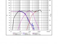
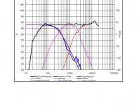
the first place, I'm talking about the bass units 2kHz+ peaks here.
FWIW IMO the bass units "problems" begin at 700/800Hz, this is
obviously where the transition from "pistonic" to "break up" mode
occurs, it is very well controlled though for another octave or so.
At 30 degrees off axis - assuming the speakers are "voiced" to be
used with no toe-in (my personal preference) the "peaks" are near
the actual "target" response (what the target should be is another
issue), the 700/800hz issue remains and there nothing the c/o can
do about this, other than the intrinsic alignment, which looks fine.
I suggest fingers should be pointed elsewhere, noting that the
most critical region for "voicing" is around 3kHz, and including
off-axis behaviour is important.
You could ignore what RJB is saying, but I wouldn't .....
I would assume the bass/mid c/o is not amenable to tweaking...
🙂/sreten.
Seems there is some mindless meandering, 2R||80uF !?
The disadvantage of sims is its easy to seize on the "problem"
and try and fix it, without really confirming this is the problem in
the first place, I'm talking about the bass units 2kHz+ peaks here.
FWIW IMO the bass units "problems" begin at 700/800Hz, this is
obviously where the transition from "pistonic" to "break up" mode
occurs, it is very well controlled though for another octave or so.
At 30 degrees off axis - assuming the speakers are "voiced" to be
used with no toe-in (my personal preference) the "peaks" are near
the actual "target" response (what the target should be is another
issue), the 700/800hz issue remains and there nothing the c/o can
do about this, other than the intrinsic alignment, which looks fine.
I suggest fingers should be pointed elsewhere, noting that the
most critical region for "voicing" is around 3kHz, and including
off-axis behaviour is important.
......
and even with if you have full measurement capabilities the FRD
tools make it much easier to adjust the crossover in the hard to
measure 100-500 region where most woofers cross with midranges.
......
......
So based on those two examples it appears that getting the
tweeter level right is the primary problem with designing a
crossover based on pure simulation so I would recommend
that you buy several resistors in order to experiment with
different tweeter L-pad values.
......
........
So this example reveals several things about the value of using
FRD tools to design a crossover. It shows that the tools can be
very accurate with the most common required adjustment being
the tweeter attenuation. It also shows that even if you have
measurement capabilities the simulated responses tend to be
more accurate in the sub 500 Hz region where taking accurate
measurements can be very difficult and this can be very critical
when designing a three way speaker.
........
You could ignore what RJB is saying, but I wouldn't .....
I would assume the bass/mid c/o is not amenable to tweaking...
🙂/sreten.
Thats how we are different in that I always listen with the speakers pointing directly at my listening position ... nothing else goes ... listening offaxis I lack the precision that I prefer ... well, actually the front baffle is slanted, so I do listen slightly offaxis
But getting tweeter level right, ofcourse, but thats a more simple thing and only the beginning
So Sreten, what do think about the small bumps around 2khz on both tweeter and midrange ... could it be something related to interaction in the filter, or is it just a strange coincidense that it shows on both drivers ... or maybe a baffle issue ... or phase related ?
Omni,
Re: your post # 766, quote " is it possible to eliminate those spikes down there at 2000 Hz? "
did you see my post # 748 ? - I know you have been very busy!
Their might be multiple (parallel LCR) solutions! What is optimal , IS what sounds best for you and doesn't blow up your amp! As Sreten says, identifying and fixing the fundamental problem is most important, then imho, 'voicing' / tweaking for best personal sound is secondary, whether it be resistors (or stereo Lpads) on different parallel components or the M/T drivers themselves.
Sreten,
I've read your various comments, many thanks, but surely Omni's SLS' very ragged in-box reponse needs some very serious control by the xo at breakup? I think Zaph does it very precisely with his L18's etc.
Unfortunately, about 45 pages of this thread have disappeared!, but , if you don't mind , regarding the TangBand W4-1337SA
'full-range' .. your previous comment was something like a 'mechanical treble diffuser'? If I remember rightly.... Which I assume you to mean ... its treble ability is rubbish? But Zaph suggests it might be ok full range with treble xo..hmmm If I could buy just two of those , with my P25 10" Vifa's ...and it sounds ok...I'm laughing! But Zaph doesn't accept emails. So my dilemma, again..., but the neo Titanium TB might be more useful to me than the dedicated SeAS MCA15 Mids. Dunno!.... thanks, again grant
About the TB driver ... I reckon you will have to try it, to find out if you like it or not
Just realized that I have burned 1/2 pound of silver solder on this xo alone ... wonder how many combinations I have tried by now ... I must be totally flaming mad crazy
Just realized that I have burned 1/2 pound of silver solder on this xo alone ... wonder how many combinations I have tried by now ... I must be totally flaming mad crazy
grantnsw said:
Sreten,
I've read your various comments, many thanks, but surely Omni's SLS'
very ragged in-box reponse needs some very serious control by the
xo at breakup? I think Zaph does it very precisely with his L18's etc.
The L18 breakup is controlled to be about 35 dB down.

Far worse "problem" above than the SLS has :
The SLS will not cause as much distortion peaking as the L18,
so IM0 30db or so down should be fine.
🙂/sreten.
tinitus said:
So Sreten, what do think about the small bumps around 2khz on both
tweeter and midrange ... could it be something related to interaction
in the filter, or is it just a strange coincidense that it shows on both
drivers ... or maybe a baffle issue ... or phase related ?
Hmmm......
One of those burning questions some people have to have answered.
For the H1216 the 2kHz bump is all too real, look at the off axis response.
For the tweeter i've no idea where the "discontinuity" come from.
However as these are in a simulation, it is easy to "experiment"
and find the process responsible, and then ascertain the likely
accuracy of said process before you set about fixing it.
🙂/sreten.
Well, i bet there is a phase issue related to the breakup around 2khz, which hits also around the xo point of mid and tweeter
solve it and you will be rewarded with much better phase coherence
In Zaphs speaker, the breakup is around 8-10khz, and may be less important, but I would solve that too
solve it and you will be rewarded with much better phase coherence
In Zaphs speaker, the breakup is around 8-10khz, and may be less important, but I would solve that too
Good stuff...............Many avenues and thoughts to ponder........Tinitus, I got your message about reducing the cap size ................This will increase the size of the inductor, obviously........This is the direction that I will start with........Vance Dickasons writing on p-traps follows along that line of thinking, stating that if you want to reduce the peaks in the woofer at higher frequencies beyond the stopband, that the way to address it is to utilize larger inductors..............This brings me to this question, Tinitus.............What would you suggest as the LARGEST value inductor to use? What would be an acceptable DCR limit for this inductor, so as to not lose control over the damping of the woofer?..............I saw on rjbaudio.com a p-trap for The Extremist using the following components.......Inductor: 1.5mH..........Cap30uF.......Resistor:10ohms...........used to relieve a rising frequeny response in the woofer..................I will continue to work on 1 issue at a time as we have spoken about..No sense in getting overwhelmed about several things at once...........Grant, I am gonna have to review your post, as I can't honestly say that I remember it............I will be in touch here, again shortly......Omni
Grant, I just took notes on your post 748.........I will be getting home earlier tonite and sim it, and I can provide you impedance information.......Thank you very much for bringing it to my attention...............Omni
1.5mH sounds a bit big, and I guess it is part of BSC in the design, or maybe used on a PA woofer
But we should remember that speaker impedance has influence on the values
How big and how much DC resistanse your design can manage depends of the DC resistanse of your present series filter inductor, and further on your box size, and how your bass is at the present, do you want more bass and can you bare to loose some controll
If you like your bass as it is, I would use as small a inductor as possible... but your simulation should tell you how much is needed
I dont think that DC values around 0.25ohm would present any problem
Tinitus, I like your thinking, here...... .25 seems a reasonable number. I will be back to working on the notch........Got a plan, I hope you stay tuned.. I want to maintain control of the damping of the woofer.............Currently it thumps nicely, and is very transient, and I wanna keep it that way.................Omni
- Status
- Not open for further replies.
- Home
- Loudspeakers
- Multi-Way
- 3way XO help greatly appreciated!