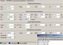
I see. Sometimes I start from scratch. Write the numbers you have in a paper (the picture is fine). Now as you must know Qts total of Qms mechanical and Qes electrical. So, if you erase them and start with the one they say in their instructions and let the computer do the math, you will be happy with the result. It takes some time because you are adding more information to the one that is already there...
My friend, Tinitus....Yes it has been quiet here lately..........I have been in touch with Grant on E mail, as we have become good friends...............You may have read earlier in this thread of my iron core inductors being a bit low from the 8 mH that I ordered........Here is the latest............My Solen air cores for the upper mid and tweeters measures spot on which is perfect for me.........The Iron cores measured 7.6-7.75 mH for the 8mH value that I ordered.......The 5.5mH iron cores measured out to about 5.35mH...........The wierd thing is that on any given day that I would measure these iron cores, I would get a differing value........So I talked to the vendor about it and we agreed that I would do a listening test with the option of swapping for new inductors, if I was not satisfied.................Here's what I have done, and where I am at to this point.........I took my measurements of the iron cores and resimulated in my crossover designer................The magic never seems to quit...Here's what happened..........I was able to get a smoother summed response, with a 1/2 db gain in SPL.........Overall SPL is now at 88dB..I made a few adjustments in some of the series resistors AND some of the resistors in series with the parallel components..............and VOILA........the upper end not only smoothed out a bit, but gained enough to smooth out the entire response curve.............Minimum impedance of the system is at 5.18 ohms............which occurs in the higher freqency drivers.........Since I have extra components to tweak with, I will be able to make appropriate changes if need be............One thing I must keep in perspective is that up to now, I am only dealing with simulations, and reality may differ from these simulations..........Here's where I am at, now..........Boxes filled with damping material, and the back is sealed............I am in the process of wiring up the crossover and mounting drivers, currently..........Work and other personal obligations have created delays in finishing "Frankie"........I deeply appreciate the insights you have provided on this thread, as we are getting ever so close to Frankies' opening nite, which will come hopefully this weekend.........I can't wait to post pictures and my initial listening impressions here very shortly.............Your interest, investment in sharing the ART, and support along with Grants' stallwart friendship, input, and walking the path alongside, and absolutely........ Sretens input { especially links } is a gift I truly treasure.................So as far as things are at the moment......there is no trouble..................yet.........lol..........I will post my impressions upon hearing my inaugural session with Frankie...............of which, there is a little bit of all of you guys...........Thank you for keeping it Alive.............Omni............
Hi Omni , Tinitus , Sreten and anyone else reading this thread,
Thanks for the update, Omni, you've done extremely well so far! The iron cores may indeed be under 'specced', but it just occurred to me ...a question please... did you measure them on different days
relative to any switched on electronic equipment? Its just a thought that maybe proximity to a TV set or something when you measured one day might (?) change the result due to induced magnetic field?
I could be talking rubbish here!... lol, so take it with a 'grain of salt'!
Re: 'magic never seems to quit' - wow, thats fantastic! There's heaps of serendipity happening for you! Great stuff. As you have diligently followed the FRD tools procedures which Roman B. says the outcome will be very close (within several dB?) compared to properly measured results... I have every confidence that your new tweaked simulations will translate into actual aural Nirvana! I borrowed aural Nirvana from either Troels or Zaph, can't remember who! When the time comes, we'll celebrate your success! And
hopefully discuss the sound at length, also tweaking (if needed) etc.
I have to laugh when I admit that my project is still 'on hold' due to funds having to be diverted elsewhere. Oh well. As soon as time permits, I'll sim Sreten's mixed series/parallel XO with Curts data files. I have closely looked at 'Curts' data simmed in *JB's* new 'all-in-one' FRD beta program and I think/hope it will be very accurate. Hopefully a new tested version of JB's 'beta' will be released soon. Cheers everyone and best wishes, grant
Hi!
I briefly read about a 'Duelund' 3 way passive xo .. before I glazed over with all the maths! hehe Would any learned person here please give a *very brief overview* synopsis in laymans terms?
That is its advantiges etc...simplified to the max if possible! I hope you don't mind me asking...thanks! grant (sorry about my spelling, its late)
Hi,
I am not skilled enough to explain the details and maths
But I think to know that his main goal was to achieve absolute phase coherense between all drivers at all frequencies
At some time many years ago he and his mate discouvered the acoustic rolloff to be more important than the "electrical"
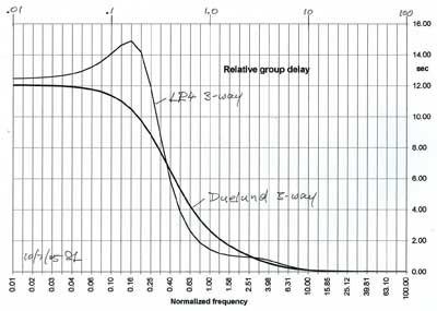
Allthough his filter in theory is a 24db or even more it can actually be converted into 12db
The slopes start slowly and gets steeper at the end, resulting in round "shoulders", which I am explained looks much like a Bessel filter
In my long year work with a Duelund filter and trying to simplify it
Its is important to have the slopes right, but it is even more important HOW you achive it
I have found that in end the most important and tricky part happens outside the drivers passband - I think that is in the hart and soul of the late Duelund
He used many years to find and devellop the needed components to reach his ultimate goal - he did have all components in the end but unfortunately died before he could finish the ultimate speaker
I am not skilled enough to explain the details and maths
But I think to know that his main goal was to achieve absolute phase coherense between all drivers at all frequencies
At some time many years ago he and his mate discouvered the acoustic rolloff to be more important than the "electrical"
Allthough his filter in theory is a 24db or even more it can actually be converted into 12db
The slopes start slowly and gets steeper at the end, resulting in round "shoulders", which I am explained looks much like a Bessel filter
In my long year work with a Duelund filter and trying to simplify it
Its is important to have the slopes right, but it is even more important HOW you achive it
I have found that in end the most important and tricky part happens outside the drivers passband - I think that is in the hart and soul of the late Duelund
He used many years to find and devellop the needed components to reach his ultimate goal - he did have all components in the end but unfortunately died before he could finish the ultimate speaker
BTW .... allthough Duelund had very high demands, he very often used quite cheap drivers, which he found often sounded better than many of the advanced designs, and if they didnt work, he made them work
he could find the most peculiar flaws on even the most expencive drivers - on the XT25 tweeter it was a bit of glue on outer edge/surround that shouldnt be there, among other more obvious things like roundings on the faceplate
he could find the most peculiar flaws on even the most expencive drivers - on the XT25 tweeter it was a bit of glue on outer edge/surround that shouldnt be there, among other more obvious things like roundings on the faceplate
grantnsw said:Hi!
I briefly read about a 'Duelund' 3 way passive xo .. before I glazed over with all the maths! hehe Would any learned person here please give a *very brief overview* synopsis in laymans terms?
That is its advantiges etc...simplified to the max if possible! I hope you don't mind me asking...thanks! grant (sorry about my spelling, its late)
If you can get it to work its shown in a nutshell above.
From http://www.linkwitzlab.com/crossovers.htm
which explains to a degree and describes approximating a=4 from
http://www.meta-gizmo.com/Tri/speak/STEEN.html
🙂/sreten.
Grant, I never did think of the place where I measure the coils, near a TV or whatnot, but now that you mention that, I can say that I was within about 5 feet from a TV sometimes, and away from it on other days............That is an interesting theory you have, which I will heed and try some measurements away from any eletronic devices.............Thank you for your thoughts.......I will keep you posted....................Omni
Hi Tinitus and Sreten. Sorry for the delay.
Tinitus , your work with Duelund is insightful! Thank you for the 'round-shoulders'. I appreciate that. As I appreciate all your other work, thank you very much!
Sreten, thanks, again! The complexity of the maths is beyond me, but I do value your input! Its maybe 'too hard basket' for me and beyond my understanding at this time. But thanks! I do value your thoughts!
Omni....cheers mate! and best wishes! You WILL have a great result! grant
tinitus said:
Allthough his filter in theory is a 24db or even more it can actually be converted into 12db
Hi,
the important thing is the mid low and high pass is 6dB/octave for
12db/octave bass and treble filters, this is the B&O "filler" concept.
They have 3 parts in the nominator, and thereby lead to a 3-way system -
second order for highpass (s2) and lowpass (1), but first order for the bandpass (2s).
Higher orders are similar, 24dB/oct bass and treble + 12dB/oct bandpass.
In general it can be said, that the bass and treble roll off are 24 dB per octave
asymptotically ruled by it Q, and likewise the middle but with 12 dB per octave.
The difficulties are mainly keeping the bandpass slopes over the overlap.
I'll also note that depending on how you approach filters, you will
get different "ideal" functions. Many of these "ideal" functions can
be similar if the parameters you are optimising are interelated.
However it is easy to generalise that low order crossovers with
wide overlap (therefore "rounded" Q's) will have superior transient
response / group delay characteristics. But getting the right
acoustic functions and avoiding vertical lobing is not so easy.
In the end its all sensible compromise, and should be based
on the actual drivers capabilities, not some theorectical ideal.
🙂/sreten.
Yes, that does "ring a bell" - it has been a hard nut to crack in practise and could explain why I ended up with only 0.3mH on midrange, with RC and notch
Main problem has all along been that every time it sounded right there has been a small but very annoying phase problem, very peculiar - but I think its solved now, at last
Duelund has always claimed that his filter could only work right with perfect drivers - its a very sensitive filter and my decision was that I would never recommend it .... takes too much work and difficult to get right, but again you are rewarded with fantastic sound
But unlike some fanatic Duelund fans, I do think that there are other ways to good sound - but only time will tell if I can do it again, with the same level of perfection, but I do have my doubts - hell, one can allways hope fore "luck" and do even better
But it will be exiting to hear from Omni, when his "Frankie", SonOfEinstein hits the scene
Tinitus,I got a boot out of your latest post.....Thanks for your generous words......I got some other hassles taken care of, and the rest of the week IS devoted to Frankie.............Will be in touch shortly...........................Omni.........
Hi Tinitus, no not too much trouble...............I had to do some creative things with the crossover pertaining to resistor mounting, along with a hectic schedule in life.............ABSOLUTELY this weekend will be Frankies' inaugural audition, so I will be posting pictures and my first impressions..............Doing the math with DCR values has required minor changes in a few resistor values, and the simulation is superior to my previous best, so hopes are high................Look this weekend for my performance comments.............I deeply appreciate your interest and wisdom, as well as Grant, Sreten, and all who have contributed...........This thread is still alive, as Frankie soon will be...................Omni
Is anyone still here? lol.... I'm sorry for my long absence!
Unfortunately my 3-way project is still temporarily stalled due to other commitments. However, I was just looking at the Seas impedance curves for the 27TFFC and 27TDFC tweeters, attached. The 27TFFC (my choice to buy) is on top, but am I right in that the Z curve peak is too high? Its nominally a 6 ohm driver, with voice coil resistance of 4.6 ohms. The graph says its over 10 ohms at about 520 Hertz? Am I missing something here please? Many thanks, grant
Unfortunately my 3-way project is still temporarily stalled due to other commitments. However, I was just looking at the Seas impedance curves for the 27TFFC and 27TDFC tweeters, attached. The 27TFFC (my choice to buy) is on top, but am I right in that the Z curve peak is too high? Its nominally a 6 ohm driver, with voice coil resistance of 4.6 ohms. The graph says its over 10 ohms at about 520 Hertz? Am I missing something here please? Many thanks, grant
Attachments
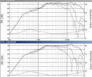
Oops, I just had another look at Zaph's Tweeter Mishmash for the TDFC and it looks the same. So, I guess the TFFC is ok too!
Grant.............I did a little research at SEAS website on the TFFC relative to the TDFC and also looked at Zaphs' website, as well as other charts and graphs of these tweeters and other reported information...........Free air resonant frequencies for TDFC and TFFC respectively are reported as : 550 Hz and 900 Hz..........With recommended minimum x-over freq. of 1500 and 2000 Hz respectively...............Obviously a lower free air resonant freq. will allow a lower minimum crossover freq, however upon looking at the graph of the TFFC, its' impedance chart looks different compared to its' reported TS parameters for resonant freq................Or I don't know how to interpret response graphs..........I hope that's not the case....................A large part of Frankie was developed around those charts....as you well know............................Almost there...................Omni
Hi Omni,
I guess what had me miffed is that both these tweeters use Ferrofluid so I was a little surprised to see the 27TFFC resonance Z 'spike' over 10 ohms. Its lower in the 27TDFC later 'model', so improvements have been made. I recently read somewhere that its best to use a driver with the smoothest Z curve? (Might have been Lynn Olson's new Ariel thread?)
The March '95 27TFFC has Fs 900 but the Aug 2006 spec says 550Hz same as 27TDFC ( 27TFFC_881ny06.pdf ).
The testing pages I've read for the TDFC rate it very well, but as yet I've found no distortion info relating it directly to the TFFC. But hey, they're both Seas so they must be good!
Looking forward to learn of your first system audition! grant
Forgot to mention this (I'm probably repeating the obvious), that many? high end tweeters don't use ferrofluid at all, somehow they keep Z at Fs low....but how? I need to read more! lol
- Status
- Not open for further replies.
- Home
- Loudspeakers
- Multi-Way
- 3way XO help greatly appreciated!