Thanks Omni, .....the second sim with 8mH would be the one... seems just a tiny bit smoother 😉
Well, I might also want just a tiny little bit smaller series inductor on midrange
Well, I might also want just a tiny little bit smaller series inductor on midrange
tinitus said:
What has actually become very clear is that sim software is a very
usefull tool - but also that its not that simple and easy, and still must
be supplemented with some experience, as it often is in many cases.
Hi,
So true. To use a Simulator properly you must understand the
phenomenon it is simulating to understand the simulator. If
you don't understand the phenomenon you will have no idea
whether what the simulator is telling you makes sense or not.
(For example you can design "perfect" circuits in electronic
simulators that in reality are hopelessly impractical. The
simulator cannot teach you understanding of details.)
I've read through http://www.rjbaudio.com/Audiofiles/FRDtools.html
again, most of it seems there but the instructions are very compact.
I''ll note there are instructions for generating phase information
if this in not available for both acoustic (frd) and impedance (zma).
It seems the phase step is the most confusing, but this information
must be near correct for accurate summation in the c/o regions.
Also see :
http://www.rjbaudio.com/Audiofiles/SWtutorial.html
http://www.rjbaudio.com/Audiofiles/FRDtools example2.html
http://www.rjbaudio.com/Audiofiles/driver offset calculator.html
The whole point is that speaker design is not simple and easy, and
any cookbook or methodology that describes it simply, is simply wrong.
Whilst simulating is not easy - its far easier than trial by building,
which simulation also shows if the design is wrong in the first
place no amount of tweaking / fiddling by ear will fix it.
🙂/sreten.
Omni, G'Day!
I'm glad to hear that everything is on-track for your project and looking forward to the photos. You might as well stand next to them as the proud creator! <grin> Nah, I guess not - internet anonymity is probably important these days. I have a small question please about, quote: "These high value capacitors will have to be parallel bypass creations in some areas, so I am doing the math..". Are you referring to say, the Peerless xo capacitor? If so, to get large values, caps are paralleled as you say and I would have thought the total capacitance is just the sum of values? I'm sorry if I've misunderstood, just trying to be helpful....
Btw, just for interest, re crossover building: Troels and Roman's sites have some interesting tips on xo construction, including orientation of coils, "star-earthing" etc. You probably have already read them!
Well, I don't know that my enthusiasm is unbridled! Several times lately I've thought all this is beyond my ability. I had a long read of some text only FRC tools info and was completely bewildered! I take my hat off to you for getting it all working! To me it might as well have been in Hieroglyphics!
Sreten has been extremely helpful as usual, the problem is still my inability to understand concepts, but I will pursue this hobby with my best tenacity as long as I can! lol Hopefully soon, "the penny will drop"!
Tinitus, Hi!
I think you are indeed correct re simulation software. It does seem to have great benefits but will never replace experience, 'imho'. A lot of it to me, appears very complicated as well. I am inspired that people like yourself have achieved such terrific results from a tweaking methodology, and I would definitely like to learn from your experience. Its great to see you here and I hope you are well
and making beautiful music on your violins!
Hello Sreten, so many thank-you's to you!
Your guidance over months has been invaluable! Thank you so much for your patience with me and my 'dumb' questions! Unfortunately I'm still having some difficulty with the mid baffle-step scenario.
Best wishes to all, grant
Sreten, Wow, I just read your last post!
Great stuff!, thanks for the links, especially for the generating phase information. I'll check them all tomorrow...very much appreciated..grant
Great stuff!, thanks for the links, especially for the generating phase information. I'll check them all tomorrow...very much appreciated..grant
Tinitus, Thank you for your assessment, and I will follow per your recommendations...............In an earlier crossover schematic. you mentioned about that mid series inductor.........At that time, it was at .93 mH and you suggested that I lower it, which I did, to .84 mH, which you see now..........It made a definate improvement. Per your latest posted suggestion, I will experiment, and take it a bit lower to see if there is any more room for improvement..........Thank you..........Grant, Yes you are correct. Putting the capacitors in parallel to each other does sum up to the total value of their capacitances. I will need to do this with the series capacitor for the midbass, though I would rather not, in this instance. However, of the capacitors I am using, they are not available in 65 uF. I will need to create the 65 uF by combining values. For the Perrless shunt capacitor, I may simply use an 80 uF available from Solen..............I have not read the crossover tips you mentioned, but will check them out, as I am always looking for the better ways to create improvement. I have read about Star Earthing in crossovers, and if the leads on my components will allow this, I intend on employing this practice.........Grant, again, thank you for your comments. I am not certain it's all working, but will find out shortly...........I will, however, comment on the simulation philosophy discussion........As per most comments here about simulation, I agree that it is not easy, and though tutorials may appear to be compact, it is through the experience of actually doing it, that I have learned. Understanding of details, for me, has come from actually performing the simulations, and consulting with you guys, here, on this thread..............With the particular FRC tools I have incorporated, there goes a glimmer of hope for which Roman at rjbaudio is responsible........He mentions, in his materials, that he has experimented with actual measurements of the speakers he has created by using the FRC tools, and found them to be extremely close, but not exact, to within 1 to 2 dB of his target............To the person with no measurement tools, or who cannot afford measurement tools, this method appears to be the next best thing, compared to simply relying on textbook formulas.........Being that I view speaker building as much as an Art, if not moreso, than a Science, it appears that there will always be unknowns in the mix..............However, it is the search for the unknowns, with your help, which has proven to provide great joy in this endeavor.................With a failing vision throughout his years, some of Degas' most beautiful works were created................Not perfect......but certainly beautiful...............Respectfully.................Omni
grantnsw said:
Unfortunately I'm still having some difficulty with the mid baffle-step scenario.
Hi,
reduce the the problerm to only its components e.g.
Sealed box with 8" bass unit and sealed 3" mid/treble driver.
One way of approaching BSC :
Get a bass driver 4dB to 6dB more sensitive than the mid/treble or
attenuate the mid/treble to 4 to 6 dB lower than the bass unit.
Then cross them over (1st order series say) near the centre frequency
of the baffle step (actually somewhat lower in practise). You will get a
response that approximately compensates for the baffle step automatically.
🙂/sreten.
Hi Sreten,
thank you for your last post!
RE: "Get a bass driver 4dB to 6dB more sensitive than the mid/treble or attenuate the mid/treble to 4 to 6 dB lower than the bass unit." <politely> yes, I do understand this, thank you! - I'll need to pad down the MCA.
My question was based on your previous comment about simming the MCA in 'the Edge'.
Unfortunately, at the time I mis-read your answer - so sorry!
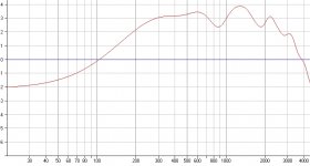
Your reply was Quote: " *** No use your box / baffle, and modify response for your mid-box roll-of." Thanks!, I just did this (excluding modifying rolloff) in "the Edge" . The result is attached for a 3inch driver in my Vifa P25 box.
(For my normal listening position I put the microphone at 3 metres distance and centred it vertically at 1 metre ear height with 1.5 metre horizontal offset to each speaker (3m total)). The ripple looks acceptably minimal to me.
So, if the 'mike' placement is ok, then I need to *add?* the BStep curve from 100 to 4000Hz to Troels infinite baffle response?
Sorry, but I'm a bit confused here, because you said it would be "more likely be a subtraction"- I'm struggling with this because
if an infinite baffle has no baffle step (Troels graph), and I'm modeling in a smaller box/baffle with a BStep increase, then surely it must be added? As usual, I might have entirely missed the point due to inexperience!
I can SPLTrace both the Edge 'BS' and Troels and hopefully find a way to 'sum' them in SW, if not then manually I suppose.
Does this sound feasible please Sreten? The viability of my project kinda hinges on getting this right. Hopefully then I can pursue
your suggested series/parallel mixed xo topology. many thanks , grant
thank you for your last post!
RE: "Get a bass driver 4dB to 6dB more sensitive than the mid/treble or attenuate the mid/treble to 4 to 6 dB lower than the bass unit." <politely> yes, I do understand this, thank you! - I'll need to pad down the MCA.
My question was based on your previous comment about simming the MCA in 'the Edge'.
Unfortunately, at the time I mis-read your answer - so sorry!
Your reply was Quote: " *** No use your box / baffle, and modify response for your mid-box roll-of." Thanks!, I just did this (excluding modifying rolloff) in "the Edge" . The result is attached for a 3inch driver in my Vifa P25 box.
(For my normal listening position I put the microphone at 3 metres distance and centred it vertically at 1 metre ear height with 1.5 metre horizontal offset to each speaker (3m total)). The ripple looks acceptably minimal to me.
So, if the 'mike' placement is ok, then I need to *add?* the BStep curve from 100 to 4000Hz to Troels infinite baffle response?
Sorry, but I'm a bit confused here, because you said it would be "more likely be a subtraction"- I'm struggling with this because
if an infinite baffle has no baffle step (Troels graph), and I'm modeling in a smaller box/baffle with a BStep increase, then surely it must be added? As usual, I might have entirely missed the point due to inexperience!
I can SPLTrace both the Edge 'BS' and Troels and hopefully find a way to 'sum' them in SW, if not then manually I suppose.
Does this sound feasible please Sreten? The viability of my project kinda hinges on getting this right. Hopefully then I can pursue
your suggested series/parallel mixed xo topology. many thanks , grant
Attachments
Hi Grant,
you need to read through RB instructions very carefully and follow
them to the letter or what he's saying might not make sense.
Deals with using TGs measurements on his baffle.
🙂/sreten.
you need to read through RB instructions very carefully and follow
them to the letter or what he's saying might not make sense.
The "Baffle Measure" column should be set to match the baffle type that was used by the manufacturer when the driver's measurements were taken. If the baffle size is finite and is known then import the corresponding baffle response file that was generated by the BDS spreadsheet.
Deals with using TGs measurements on his baffle.
🙂/sreten.
Omni,
Thanks, kind sentiments indeed. Its always a pleasure to read your posts! ..........And everyone elses of course...........!
Regarding 'star-earthing' (I could be wrong here) but I think the idea is to reduce induced mains 'hum' from close power cables, etc. At audio frequencies, maybe a short lead extension won't cause
any problems as long as all the * - * leads go to the same physical point, ie 'ground'. I also read that for tweaking, alligator clips aren't advisable, its better to use cheaper screw-down terminal blocks instead - gives a lower resistance connection evidently.
<*off topic*> Your comments on Degas was interesting... from memory Monet's vision went reddish in his old age, but then he also produced his best works?....its only what I read! I'm not really a fine-art-buff, lol.
grant (I wrote more for fun but decided to delete it...)
Grant: I think you are in the correct ballpark on star grounding............It is also the experience of some well respected speaker builders that applying the star ground concept to the + side of the crossover, called star inputting, leads to far better imaging, superior clarity, and a much lower noise floor. So if space permits, I will be experimenting with that, as well..........Sounds like you are in the depths of your project. I hope you are having fun.......................Omni
I am not sure about star ground...... it will be a mess
But maybe seperate star ground for each section ....
I would say, build it exsactly like you draw it ..... each section should have its own ground line from speaker terminals.... use solid core cobber wire
But maybe seperate star ground for each section ....
I would say, build it exsactly like you draw it ..... each section should have its own ground line from speaker terminals.... use solid core cobber wire
Hi Sreten, thanks for your input.
I had saved and read all of Roman's Audiofile links before, but I must admit I had forgotten the significance of the "Driver Offset Calculator' ...I must try it and use the results for my project.
With respect, I'm unsure of the best way to meaningfully respond to your last 3? replies as I'm still confused...but here goes. ( I hope my uninformed questions are ok to ask...again)
Of the FRC Tools , the only one I can use is Speaker Workshop as it doesn't require MS Excel.
So, I initially wondered if it would be possible to somehow use the Seas response in the 20L test-box, and find an alternate BS simulator....enter 'the Edge'. You very kindly suggested that I use Troels PMS I.Baffle response from his MCA modeling - excellent thank you! So, I modeled the MCA for BS/diffraction in my enclosure at my listening ('mike') position.
My question, please, is this: Would it be valid to try to 'combine' Troels IB graph and my graph (Bstep/diffraction from 'the Edge' for the MCA in my enclosure) to get a resultant response which
includes BS effects for my specific enclosure?
I'm hoping this is possible, and I can somehow accurately include the 4dB BS gain as shown previously.
If not, then it will mean an abrupt end to my project as tweaking with an unusable starting point will be well beyond me, I'm sure.
If my notion IS valid, then I would have thought its just a simple addition of the values from 100 to 4000Hz? To me, this seems intuitive, because: if an effect causes an increase, then it must be added in to the original.
Roman mentions that the phase data is derived from the Hilbert transform (I'm not aware of it) on the SPL data - which is what I assume FRCombiner does. So this is another obstacle for me unless there is another alternate program that doesn't use Excel.
As usual I hope you're not dismayed by reading this and I'm eager to see your reply. Thanks very much Sreten!, grant
Hi Omni and Tinitus, and Sreten of course.
Omni, re: "Sounds like you are in the depths of your project." Lol, You're right on there!!
In so deep that its nearly at the point of being canned. If my notion of adding BStep to Infinite Baffle response is invalid, then its a big 'fizzer'! Oh well, I did learn a lot from all the great people in here.
(Unfortunately there is no way I can afford the whole MS 'Office Suite' just to get Excel.)
Interestingly I read yesterday that in the USA MS *was* giving away *free* Office 2007 and Vista! But not here. The Office-2007 file types are evidently incompatible with previous versions! Whoa!
I thought 'star-inputting' as you call it was a routine procedure? That each drivers xo goes to the same * + * physical terminal input 'lug'. Well, thats what I've done in the past and I'm glad to hear that it may have some benefits too. Re: 'star-earthing': this link ( I lost the others...)
www.parts-express.com/projectshowcase/xover/xover.html is interesting but annoying pop-up.
Tinitus, Hi
No doubt you've heard of the 1743 Carrodus? I'll be able to hear it soon, wow! Please see this:
http://au.news.yahoo.com/070130/2/128ns.html Even better than a Stradivarius?
Re: "I am not sure about star ground...... it will be a mess", ...well maybe not necessarily, 'imho'. If the coils are placed properly with respect to orientation to reduce interference, other parts placed 'visually nicely', the resistors are raised above the board to dissipate heat and leads extended as required then I reckon it could look quite good? Just a thought? Best wishes to all.. grant
(this assumes extending leads still makes a 'star'?)
Grant, you have come too far to give up now. Man, you are committed.................If 4 dB is your difference between drivers, could you possibly simulate your crossover with component values that will give you the 4 dB response boost for the particular driver, which you can view on the response curves that are generated in Speaker Workshop? Then tweak to sound........Just a crazy thought.....................You do have other options.......Of that I am certain..................Respectfully............Omni
Thanks Omni,
Yes I know you're right - thanks for your encouragement; I just get frustrated sometimes when I can't understand things or can't find an alternate way of doing something. I should have just thought it and not typed it!
The 4db I mentioned is the MCA BS/diffraction in my box from the 'Edge', its not a difference between drivers. Your idea wasn't a ' crazy thought ' - it seems sound (lol) to me. Adding an average of 3dB BS
to Troels MCA IBaffle graph will give an average of about 93dB from say 300-3000 Hz. This augers well for the P25 woofer which is at 90dB at 300Hz. Yes I'm sure there will be ways around things....
Cheers Omni, grant
Hi,
Both bass and mid drivers are ~ 90dB / 2.83 V on a large baffle.
Both will produce ~ 84dB / 2.83 V after baffle step before bass roll-off.
If you use say 4dB baffle step compensation this means the midrange
and treble needs to be attenuated to 86dB / 2.83 V - but attenuating
a mid raises its bass Q, which is highish because of the mid volume.
If your getting confused :
- simply use the c/o and mid / treble drivers here :
http://www.troelsgravesen.dk/3WClassic.htm
Will not not be too far off - unlike cookbook crossovers.
🙂/sreten.
HI Omni, I'd like to ask your opinion on the following, please....
In an attempt to resolve my dilemma of subtracting/adding B.Step from/to (respectively?) small closed box manufacturers data OR tested Infinite Baffle data (eg Troels MCA)....
I decided to look at your CA15 graphs from your FRC Tools simulations, to try get get an idea of what's going on. Pleas see the attached - I hope its self explanatory?
Assumptions:
1/ An infinite baffle (to a driver) has no Baffle Step?
2/ A 'small-ish' baffle-dimensioned 20 Litre box will have a maximum BStep from 3.5 to 8.5 dB including maximum diffraction ripple of +-2.5dB, i.e., 6 +- 2.5 dB from 100 to 4000 Hz.
3/ For a particular driver as the baffle dimensions approach the size of an Infinite Baffle, then I assume the BS effect progressively decreases?
So I presume for your CA as shown, the FRC Tools sequence is this? :
The 20 L box baffle step is calculated and then subtracted from the Seas test data. The baffle step for your new larger box ( 3? cubic feet) is calculated and added back in to get the final CA15 frd response. Do you think this could be the process if my assumptions
are correct? If '3/' above is correct, then this might explain why seemingly the full BS is not subtracted (some is added back in from the new box effect maybe?)
I hope this makes sense! Any comments greatly appreciated! Thanks Omni, grant
Attachments
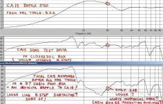
Grant, The baffle and box volume are 2 different issues that are handled seperately in the FRC tools............For the box volume issue, UNIBOX is used........First: the manufacturer parameter of box volume is entered in, along with TS parameters and other conditions considering leakage, damping amounts and whether it is sealed or vented, and then an frd. file and a zma file is created................Then, my box conditions, along with all other information pertaining to my box conditions that was entered in the manufacturers simulation, is entered into the program and another frd file and zma file is created........ Example: The manufacturers box volume for its' measurements was 20 liters for the CA15RLY..........My box conditions are 15 liters. These files are set aside.............The BAFFLE SIMULATOR Program works in a similar fashion and, again, an frd file and zma file is created for the manufacturers baffle conditions, and another frd file and zma fileis created for my baffle conditions.................These files are set aside...........This is where the FREQUENCY COMBINER Program comes in. The frd files along with the zma impedance files of the MANUFACTURER {that were created earlier} are entered into the FREQUENCY COMBINER Program. Then the frd files and zma impedance files from MY box and baffle conditions {that were created earlier}are entered into the FREQUENCY COMBINER Program and all the additions and subtractions are done, thereby creating new frd and zma files, which are used for the crossover simulations. Hopefully these final files are optimized to fit my particular box and baffle conditions........ These files I chose to call "final response" files................So in essence, we are taking the Manufactures specs and combining them with the enclosure and baffle specs {that I designed} in order to create a custom set of response files that are used to design an optimized crossover that will operate in my particular box and baffle design...........From the bottom 2 graphs: it appears that the SeasCAfinalresponsedfalt.frd graph is 2 db down from the CA SEAS test DATA..............The reason for this drop, I would surmise, is the shape of my particular baffle being a bit narrower than the manufactures baffle. I also observe that between 1K and 2K the final response frd is 1 to 3 dB down compared to the CA SEAS TEST DATA..............Again, this may be attributed to the pyramid shape and relative narrowness of my baffle, compared to the manufacturers baffle. I don't know how significant this will be when it comes to SPL when my speakers are complete..........HOWEVER...........It is my understanding that given all this information, that the FRC tools are used to determine these responses, combine them, then create the custom files used to simulate the crossover, thereby maximizing the speakers performance, given my particular design criteria.........AND/OR..........Allow the user to create a design, with the tools PRIOR to building the Box............I designed my box and baffle, and chose the particular drivers BEFORE using the FRC tools. These tools can {and were probably created} in order to create simulations BEFORE committing to a particular box design and drivers...............So you might say that my approach may be considered *** backwards, or "reverse engineering" {if I want to euphemize it}..............lol.............This is what makes this endeavor so exciting..............The thrill of working in the dark, and consorting with the likes of You, Tinitus, and Sreten, with high hopes of creating something splendid.........I hope this helps...............Keep in touch.................Respectfully.......Omni
Hi Sreten, thank you.
On page 45 you kindly described a way of approaching baffle step compensation (BSC).
But before I can even consider compensation, I need to understand the fundamentals of BS.
From what I have read so far (and still reading) about BS, that is to say what I THINK I understand, is that it causes an overall gain in SPL in boxes with baffles physically smaller than 'infinite' ( considering driver size and frequency ). For example, a Seas 20L 'finite baffle' test box WILL include BS whereas imho Troels G's P.M.S. MCA Infinite Baffle graph won't. I need to sort this out before I feel confident to progress. I'll search the forum and re-read the resouces I have.
Thanks for your comment on using Troels 3WayClassic xo's for my situation. I'll compare both mids responses and model the 3WayC mid in 'the Edge' and compare it to Troels P.M.S. MCA15 I.B. graph for learnings sake. thanks grant (if 'bystanders' are reading this, please note that my comments are probably inaccurate - thanks)
- Status
- Not open for further replies.
- Home
- Loudspeakers
- Multi-Way
- 3way XO help greatly appreciated!