Hi,
there are many ways of trying to define the performance of c/o filters,
and "transient perfect " or near "transient perfect " is one of them for
higher order filters, realisation of them in practise is difficult.
A very complex subject, but as I've said before it is best not to start
out with a a target function, its better to use whatever works with
the drivers. If this happens to be a relatively simple crossover with
slow acoustic transitions between the drivers then the transient
performance will be good by default, if not necessarily "perfect".
90dB midrange sounds too much if baffle step is included.
🙂/sreten.
Hi Sreten,
Yes it looks like Transient Perfect xo's and T/M infinite baffles are too complex for me. I'd be better 'served' by following more conventional designs. Thanks for your advice.
I'm wondering now, (as I still don't have MS Excel to run most of the FRConsortium tools) whether I could get some good results from Svante's 'the Edge'? I know you don't do 'Sims', but would you have any ideas on how I could 'get' electrical/acoustic phase data 'into' the S.W. zma/frd files respectively without using FRCombiner? Is this possible? Yes, its probably a silly question, but I'm kind of hampered to pursue this otherwise if I don't know the phase issues as you mentioned.
(Yes, 90dB from my last graph might be too optimistic).
I hope these questions don't dismay you? <politely> thanks! grant
Hi! Is anyone still here?
I've been using Svante's 'the Edge' to model baffle step/diffraction for my enclosures. Because of the driver placements on the baffle, it seems that the woofer is most affected (understandably) then
the mid and the tweeter barely at all (but I guess this makes sense, as M&T are approximately 'golden-ratio' spacing).
So, because I don't have access to all the 'FRC-Tools', I'm wondering if the following could be a viable approach? 'the Edge' suggests a 4mH choke and 6 ohm resitor (in parallel) contour network. The mid and woof xo's would connect to this and the tweeter xo would connect directly to the source. Would this have any merit do you think as long as the 4mH has a very low DCR? thanks, grant
Wow, 10,000 page views - where is everyone?
Hi,
No. you builld BSC into the bass mid crossover. Decide the amount of
BSC you want - say 4dB. Take 4dB off the bass units sensitivity, this
gives you the mid sensitivity. Attenuate the mid to suit. Note that
this will affect its high pass box Q. If the mids sensitivity is too low
you've got the wrong mid unit for the bass unit, its usually higher.
🙂/sreten.
Hi Sreten,
Just to clarify for me please, does "No. you builld BSC into the bass mid crossover"... I assume this means the bass xo (LP of course) AND the mid's HP xo? If this is the case, then this is maybe what I might have
been doing already in the simulations to match SPL's? So, if BSC is built into the crossover, then would this eliminate the need for baffle-step programs like say BDS? and hence 'combiner' type progs do
you think?
With 6dB BSC 'off' the P25 SPL it looks like I might get 88db for the MCA15 (and overall). Many thanks for your support! grant
Hi Omni,
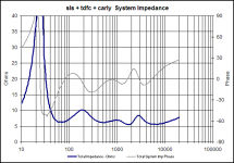
given that the y-axes are different, I'd say the two are almost identical, except for a very slight phase difference at 800Hz. The impedance looks more variable due to the expanded scale, I think.
It also looks very similar to the graph I posted on page 38 (Frankie version?), which Sreten kindly remarked that it looks ok. So I guess its safe to say that everythings fine below 50Hz? But don't hold me to that! lol, grant
Hi everyone!
If there is anyone who could help me with this, I'd be very grateful!
Ok, IF Baffle-Step Compensation (BSC) CAN be 'negated' in the crossover, then why is it necessary to use simulation programs like the FRC-Tools'? Sorry, but I just don't understand? Why would 'you' go to all the bother IF SPL matching could be done in the crossover? I really don't know. Help! lol
I'm all for simulation programs, but I'm wondering, (for ppl like me who don't have MS Excel) if a satisfactory outcome can be obtained with Speaker Workshop alone (S.W.)? Sreten and Tinitus both don't use software, and have excellent results. The other problem I have is the 'electrical phase' data input to S.W. Can anyone help me with this please? grant
Hi,
if you have measurement curves with drivers in the real cabinets
if taken correctly they will include BSC and diffraction effects.
The FRC tools simulate what happens to a driver with an idealised
flat response when mounted on a very large plane, when mounted
in the box or baffle.
The methodology outlined assumes you have no measurements
and only "in-wall" responses (by far the most common) to go on.
🙂/sreten.
Thanks Sreten,
It was foolish of me to consider that a pragmatic(?) approach might yield an acceptable result.
The P25 was measured in a 50L (closed?) box and the MCA15 in a 20L closed box, both with unknown baffle dimensions. So, thank you, measurements for my bass/mid boxes would indeed give the best result followed by using FRC Tools, the nest best option. Which from memory Roman B. said that the FRC results were within +- 2dB if done correctly, of properly measured values.
So it looks like I've got to buy the complete MS Office suite as I think measurements are beyond me. I suppose tweaking could be an option, but I would need to be at least in the ball-park first, and for me
it would be very hit-and-miss affair. grant
Hi,
the definition of a pragmatic approach is one that yields acceptable results.
The P25 is very likely measured in a box with similar baffle dimensions
to your speakers, therefore you can use the manafacturers specs and
assume they include the effects of baffle step for your enclosure.
For the mid unit you've indicated your box causes minimal ripple.
However the manafacturers specs are in the wrong box and include
ripple effects.
So what you need in measurements on a large baffle and then add
simulated baffle step effects to this. Then cross the two drivers over.
As stated before getting the phase info correct is a complication, but
mid out of phase should cause dips. You can get a lot out of test files /
CDs with 1/3 octave bands, warble tones etc using your ears.
I'd copy Troels mid/treble c/o with L-pads on both drivers (or bi-amp
with separate level controls for bass and mid/treble), then the only
complication is the bass mid c/o, which may work with 1st order series,
(for bi-amping do it passive at line level).
🙂/sreten.
Hi Sreten, thanks!
It seems there is still a glimmer of hope then!
<I'm probably making some incorrect assumptions below>
Re: the P25 - great - I can use the published graph; but I don't quite understand your comments re: the mid Quote: "So what you need in measurements on a large baffle....", would this mean that the published 20L closed box measurements would effectively be a large baffle for the mid? If so could I then sim the MCA in 'the Edge' *in the P25-Box* to get the baffle step effect? With of course the appropriate placement of the driver on the baffle.
And quote "....and then add simulated baffle step effects to this.", I presume this would just be a numeric addition?
Re: phase, I guess you're meaning acoustic phase there. Concerning electrical phase, I presume this would be very similar to an xo sim that did not factor in baffle-step?
Thanks for the info re: Troels MT xo.
Re: Q: "only complication is the bass mid c/o,...". A mixed series/parallel design the same as you posted earlier, is what you are referring to? (with LPads on both M&T).
I'm sorry but I don't remember why a 'full' 2nd-order electrical is not appropriate here? I understood your previous analogy of series vs parallel xo's, but thats about all I know about series topologies (except maybe a little of Rod Elliots paper).
Anyway, if I can understand your helpful comments, things might be looking up in the sense that the MCA could be compensated for baffle step without using the FRC Tools and that with appropriate xo's (for each 'section') I might get a good starting point for simulation and tweaking.
Thanks Sreten, cheers...grant ...(sorry for delay in replying)
grantnsw said:Hi Sreten, thanks!
It seems there is still a glimmer of hope then!
<I'm probably making some incorrect assumptions below>
Re: the P25 - great - I can use the published graph; but I don't quite understand your comments re: the mid Quote: "So what you need in measurements on a large baffle....", would this mean that the published 20L closed box measurements would effectively be a large baffle for the mid?
******No. the measurements include the baffle step of the box.[/
Possibly use this :
[Just assume response remains flat to mid-box roll off.
If so could I then sim the MCA in 'the Edge' *in the P25-Box* to get the baffle step effect? With of course the appropriate placement of the driver on the baffle.
******* No use your box / baffle, and modify response for your
mid-box roll-of. If L- pad is needed on mid give me details - I'll tell
you how to change mid-box roll-off Q.
And quote "....and then add simulated baffle step effects to this.", I presume this would just be a numeric addition?
*******more likely a subtraction - up to 6db at low frequencies.
Re: phase, I guess you're meaning acoustic phase there.
******* Yes. Presumably offsets are used to simulate this.
Concerning electrical phase, I presume this would be very similar to an xo sim that did not factor in baffle-step?
******** Yes. electrical phase is due to c/o circuit and drivers.
Thanks for the info re: Troels MT xo.
******** C2021 and L2031 are not part of the mid/treble c/o.
Re: Q: "only complication is the bass mid c/o,...". A mixed series/parallel design the same as you posted earlier, is what you are referring to? (with LPads on both M&T).
******** Yes.
I'm sorry but I don't remember why a 'full' 2nd-order electrical is not appropriate here? I understood your previous analogy of series vs parallel xo's, but thats about all I know about series topologies (except maybe a little of Rod Elliots paper).
******** 1st order series might work and give you the slow slopes
needed to allow the c/o to also give baffle step. 2nd order parallel
will also work and you can offset frequencies, but will need to be
overdamped (Q low) to give the slow c/o slopes.
1st order Series (not parallel) is worth trying.
Anyway, if I can understand your helpful comments, things might be looking up in the sense that the MCA could be compensated for baffle step without using the FRC Tools and that with appropriate xo's (for each 'section') I might get a good starting point for simulation and tweaking.
Thanks Sreten, cheers...grant ...(sorry for delay in replying)
Sreten Hi!
thank you for your reply! <I'm slowly 'working through it'>
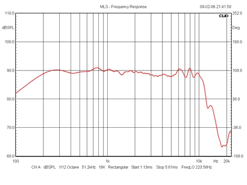
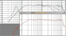
Firstly, would you please take a look at the attached graph - it shows Troels (thank you Sreten/Troels!) MCA in an infinite baffle versus the Seas specs in the 20L test box. They look so similar to me that I probably could not hear the difference? (prior to BSC)
(The red dots indicate this? --> quote: "Just assume response remains flat to mid-box roll off.")
However, I'll trace the Troels one as you suggest as it looks great and gives a slightly higher response.
My comment "sim the MCA in 'the Edge' *in the P25-Box*", was meant to suggest my Vifa enclosure. Sorry if I was unclear. I hopefully can still assume the mid baffle step should be simmed in MY reflex box. (I don't want to sound pedantic, I'm just still trying to understand and am very grateful for your patience)
Re: "I'll tell you how to change mid-box roll-off Q." - thanks, I will ask later!
Ok, I do 'the Edge' on the MCA , SPLTrace the result and either manually subtract the data from Troels, or, somehow 'combine' it in Speaker Workshop (I think there is an option for that).
Your reply to my *electrical phase* question is greatly appreciated - my overriding concern is not to blow up another amplifier! Also, I assume (once again) that if I get the 'ZDP offsets' correct then the *acoustic phase* will be right....I'm still reading your previous posts on this...
As far as the xo goes, I'm very willing to try your mixed series/parallel network when the time finally comes.
S.W. I believe will model any network. Thank you very much for your continued support! grant
(I did manage to read a text only corruption of the FRC 'Combiner' and 'BDS' help files, but I'm way out of my depth there (like taking measurements too in SW) so I'm still hoping my (pragmatic!) approach of 'close-enough-is-good-enough' might just work for me?) <*off-topic*...Federer vs Gonzalez - it will be a close tennis match?>
thank you for your reply! <I'm slowly 'working through it'>
Firstly, would you please take a look at the attached graph - it shows Troels (thank you Sreten/Troels!) MCA in an infinite baffle versus the Seas specs in the 20L test box. They look so similar to me that I probably could not hear the difference? (prior to BSC)
(The red dots indicate this? --> quote: "Just assume response remains flat to mid-box roll off.")
However, I'll trace the Troels one as you suggest as it looks great and gives a slightly higher response.
My comment "sim the MCA in 'the Edge' *in the P25-Box*", was meant to suggest my Vifa enclosure. Sorry if I was unclear. I hopefully can still assume the mid baffle step should be simmed in MY reflex box. (I don't want to sound pedantic, I'm just still trying to understand and am very grateful for your patience)
Re: "I'll tell you how to change mid-box roll-off Q." - thanks, I will ask later!
Ok, I do 'the Edge' on the MCA , SPLTrace the result and either manually subtract the data from Troels, or, somehow 'combine' it in Speaker Workshop (I think there is an option for that).
Your reply to my *electrical phase* question is greatly appreciated - my overriding concern is not to blow up another amplifier! Also, I assume (once again) that if I get the 'ZDP offsets' correct then the *acoustic phase* will be right....I'm still reading your previous posts on this...
As far as the xo goes, I'm very willing to try your mixed series/parallel network when the time finally comes.
S.W. I believe will model any network. Thank you very much for your continued support! grant
(I did manage to read a text only corruption of the FRC 'Combiner' and 'BDS' help files, but I'm way out of my depth there (like taking measurements too in SW) so I'm still hoping my (pragmatic!) approach of 'close-enough-is-good-enough' might just work for me?) <*off-topic*...Federer vs Gonzalez - it will be a close tennis match?>
Attachments
Omni, Hi!
Are you still here? How is your project going? I'm just wondering how things are progressing....
Tinitus, Hi!
I missed your reference to the Tangband previously, oops, sorry! I do thank you for your suggestion, but it seems they are unavailable here in AU, whereas the Seas is.
Best wishes to all....grant
Grant, I am still here, and am reading your progress with great interest.............Seems like you are having a blast with this, and your enthusiasm is unbridled............cool.................I am in the process of checking capacitor inventory with vendors, and intend on placing parts orders very soon.......These high value capacitors will have to be parallel bypass creations in some areas, so I am doing the math................Plus the resistor values need to be calculated out from dc resistances from inductors......I will continue to be in touch..............Hopefully it won't be too long before I post photos of Frankie...........................Omni
Nothing like good enthusiasme🙂
What has actually become very clear is that sim software is a very usefull tool - but also that its not that simple and easy, and still must be supplemented with some experience, as it often is in many cases
When I dont comment much, it doesnt mean I am not interested, it is only because I dont have anything usefull to say - but I guess we are all excited to hear about the result
Tinitus, It's refreshing to see you back, I always appreciate your input................That resistor in series with parallel components idea appears to have made a world of difference on the simulations, and I am gonna use it.....................Will you do me a favor?........................Could you go back to page 42 and check out my latest revisions? There are 2 schematics: One has an 8.6 mH inductor, and the other has an 8.0 mH inductor. They both have similar summed response, with one being a tad bit louder............In your experience, which inductor would you be inclined to start with?....The 8.6 mH or the 8.0 mH?..........Respectfully............Omni
- Status
- Not open for further replies.
- Home
- Loudspeakers
- Multi-Way
- 3way XO help greatly appreciated!