Grant, are you saying you have been experimenting with the FRC tools? Do you have microsoft Excel?...............Your response files should not be Jpg files. They are text files. The frequency response files should be .frd and your impedance files should be .zma.........How are you getting Jpg files?...........If memory serves, when you save your initial trace for both the frequency response trace and the impedance trace, it automatically saves them in the frd and zma file form...........Yes, Bagbys program does indeed have viewable phase graphs, and I am gonna post a few of them here for some interpretation along with a few response graphs and circuit diagrams........I am a bit uncertain here, but are you still having trouble figuring out the driver offset issue? Because I know that the baffle simulator requires these in order to run the program..........I hope you have gotten it clear..........if not, let me know..........Also, the only programs that will open your frequency response files and impedance files for use will be the programs that utilize them, ie, the FRC tools and crossover simulator programs..............So try simply to import them into the program you are using, from that program, don't use the clipboard to import your files to the application.......Run the applications as per the tutorials from Roman at rjbaudio: "Using FRD Consortium Tools To Design A Speaker"...It is extremely specific and only takes a time for the learning curve. If you run into more hassle, don't hesitate to Email me...........I will be glad to help..................Respectfully.........................Omni
Sorry for confusion ..... just trying to understand .... seems you are on top of it ... will try to behave myself better .... and wait for your result with patience 🙂
Omni, hi,
I agree almost entirely with the x,y and z plane displacements or offsets. My point was that for the Z-plane, the offset is measured at the horizontal centre of the voice voils, that is the 'front-plate' centre. Imho, for the scenario I mentioned (vertical flat baffle with drivers mounted on the surface, not recessed), the offsets won't be 0,0,0 because its very unlikely that the mids VC will be as far back as the woofers'. However as Sreten mentioned the difference in bass/mid VC distance will cause "next to no difference".
(oops I just remembered that Sreten doesn't do simulations...so thanks! for replying to my Q Sreten)
Re: SPLTrace/View: these are the only FRD tools that don't require Excel, I think. I re-installed SPLTrace and confirmed that all the required *.DLL files are in XP's c:windows\system32 folder, but it still
IS buggy. That is the clipboard Jpg comes up ok, the min/max values register ok, the trace begins ok, the grey area of screen increments only partially and all the resultant data is squashed down to 300Hz!
Very weird indeed! I converted *.frd to *.txt and yes indeedy, the values are 'squashed' in frequency. I read somewhere that XP has problems running some older programs, I probably need a s'ware 'patch'...<grrr!> I just tried using Roman's keyboard method, but same result and only the UP arrow works! Are you using WinXP Omni? thanks, grant
Hi,
I did ask a question earlier about the phase reference for the drivers,
I wan't sure how / what is the refrence for the absolute acoustic phase.
As I understand it the FRD files contain amplitude and phase information
measured at a fixed distance from the baffle at various angles.
Now if all the drivers have the same reference points the physical
offset of the drivers acoustic centre on axis should be included in
the phase information for the driver.
If the above is true, then for a 3 way simulated on the tweeter axis
the offsets for the midrange and bass would be the additional
distance above 1m to this reference point.
To simulate a 2m tweeter axis reference point you would need to
change the offsets. And to simulate reference points not on any
driver axis its easier to have 3 relative offsets to the point (the
point being defined by its orthogonal position in the plane of the baffle) than to calculate the path differences between the drivers.
I'll note from Zaph's ZD5 :
For me to fully understand a simulation I'd need to know exactly
what the phase information in the frd file exactly represents.
If the offsets are what I'm talking about above, and not the acoustic
centre offsets of the drivers, then apologies for not realising sooner.
(I don't actually do simulations, I try to understand the modelling.)
🙂/sreten.
I did ask a question earlier about the phase reference for the drivers,
I wan't sure how / what is the refrence for the absolute acoustic phase.
As I understand it the FRD files contain amplitude and phase information
measured at a fixed distance from the baffle at various angles.
Now if all the drivers have the same reference points the physical
offset of the drivers acoustic centre on axis should be included in
the phase information for the driver.
If the above is true, then for a 3 way simulated on the tweeter axis
the offsets for the midrange and bass would be the additional
distance above 1m to this reference point.
To simulate a 2m tweeter axis reference point you would need to
change the offsets. And to simulate reference points not on any
driver axis its easier to have 3 relative offsets to the point (the
point being defined by its orthogonal position in the plane of the baffle) than to calculate the path differences between the drivers.
I'll note from Zaph's ZD5 :
The measured response is always a dose of reality compared to the modeled response. This tells me a couple of notable things. My R22 was slightly out of spec, showing up as a half dB difference at 900hz. More importantly, I didn't screw up or lose any of my phase information. That's the most common error that results in abnormalities in the crossover region. It was particularly important that I get it right with this design since it has an electrical solution to the acoustic center mismatch. Overall, I couldn't ask for a measured response to be any closer to the modeled response.
For me to fully understand a simulation I'd need to know exactly
what the phase information in the frd file exactly represents.
If the offsets are what I'm talking about above, and not the acoustic
centre offsets of the drivers, then apologies for not realising sooner.
(I don't actually do simulations, I try to understand the modelling.)
🙂/sreten.
Sreten, Hi
It turns out that I probably will have to place M/T's in separate boxes on top of the existing boxes. I'm wondering about the relative merits of say 4-5? Litre closed MT boxes versus infinite baffles.
Also trying to find in Dickason relevant infinite baffle formulae. If say, my bass/mid xo-point is about 300Hz, I'm wondering what would be the minimum allowable baffle size for this frequency?
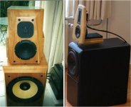
I've attached 2 Tony Gee designs, Andromeda left, Modulus I.Baffle right. The infinite baffle looks really small to me? I thought it would have had to be much larger? So I'm thinking of a kind of hybridised TroelsG/ TonyG design with a P25 - haha! could work?......Thanks Sreten!...grant
It turns out that I probably will have to place M/T's in separate boxes on top of the existing boxes. I'm wondering about the relative merits of say 4-5? Litre closed MT boxes versus infinite baffles.
Also trying to find in Dickason relevant infinite baffle formulae. If say, my bass/mid xo-point is about 300Hz, I'm wondering what would be the minimum allowable baffle size for this frequency?
I've attached 2 Tony Gee designs, Andromeda left, Modulus I.Baffle right. The infinite baffle looks really small to me? I thought it would have had to be much larger? So I'm thinking of a kind of hybridised TroelsG/ TonyG design with a P25 - haha! could work?......Thanks Sreten!...grant
Attachments
Sreten, Wow, thanks for your last post, it might take a while for me to understand the intricacies of it. I have heard of 'orthogonal' before but alas I forget (its to do with triangles, right? cf isosceles, - my antiquated dictionary doesn't have a definition - arrgh!- I must google)
As far as speaker simulation software goes, I'm just 'blindly' following what seems to have merit, and to discover the 'important stuff' along the way. FRD (ZMA) data only gives, in its RAW form amplitude(impedance) at various frequencies - thats all. *But* there's evidently a whole host of other programs that massage the data for specific situations, e.g. box designer, baffle step and diffraction etc. And I presume they consider phase issues as well? But I know nothing about them as they mostly require MS Excel which I don't have. One program SPLTrace doesn't use Excel, so I'm trying to get that working for a start.
Re: "I don't actually do simulations, I try to understand the modelling". - I'm trying my best to get there too! Thank you SO much Sreten! grant
Hi,
Look at the Calypspo files e.g. Calypso CA15.Onaxis (dataset).
The graph shows acoustic amplitude and acoustic phase.
zma shows electrical impedance Z and electrical phase.
Orthogonal = all angles 90 degrees,
i.e. the point on a plane nearest to a point in free space.
The Modulus is a highly idiosyncratic design for a particular case.
Following it would likely lead to mistakes due to wrong assumptions.
Open baffle midranges are whole new can of worms.
And much more difficult to simulate.
I'd use a Neo3 tweeter in dipole mode rather than a dome tweeter.
Troels Point 75 design would be a place to start.
🙂/sreten.
Tinitus, I am very sorry if my last post sounded harsh to you, as it was definately not intended to be. I have a high regard and respect for you and am definately in no position to talk "down" to you. I would never do that. If anything, as I reread my post, I would say that it had an air of impatience, for which I am profoundly sorry..........At any rate, I will be posting those graphs I spoke of, later tonite, And I hope you all, will give your assessments and interpretations upon viewing them..........Grant, I am running Windows XP Home version.......When you downloaded SPL Trace, did you get all 3 parts, as a new installation requires these............The DLL file you mention, I thought, came with the download, but I am not certain. I did not experience the squashing problems or problems with the Trace, and arrows, so I am sorry that I cannot give you more input........Maybe you can E mail Roman with these issues, as he was very gracious in dealing with my learning curve in all the FRC programs............I will be in touch....Respectfully............Omni
Noo, nothing to do with you at all, I am just worn out at the moment, its damm dark here at the moment - looking forward to see your work🙂
But thanks, anyway, wery nice of you
But thanks, anyway, wery nice of you
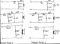
Here are a few revised xover diagrams from the last one I posted...........Tinitus: I am taking your advice about using standard value components, and what is here shows a few of those. I will finetune to standard values after I get some direction, hopefully from responses to this post..............Note the difference in the Woofer inductors.............Response graphs will be posted following this one. Any and all comments and advice is welcome, as I believe I am getting closer................Respectfully.........Omni
Attachments
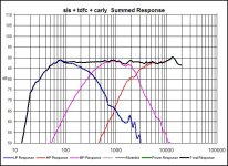
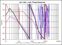
Here is a graph for the summed phase response, which also includes the responses for the individual drivers..............Please give me comments on this, as I do not know what to look for in a good phase response, and I cannot interpret this due to my lack of knowledge................This one is for Frankenstein revised 1
Attachments

Omni,
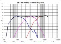
the revised 2 xo and response look good! Not sure about the phase though. Sreten posted a graph on page 38 which indicates the
electrical phase should be less than +-45degrees where the impedance is low. I hope this is correct. Does your program offer this type of phase chart? Sreten's comments on this began on page 32 I think. I hope this helps... grant
Thanks Sreten,
I'll take another look at the Calypso CA15 dataset, and also thanks for your comments on 'open' midranges. I'll also check out your Troels reference, grant
I'll take another look at the Calypso CA15 dataset, and also thanks for your comments on 'open' midranges. I'll also check out your Troels reference, grant
Hi,
Acoustic phase and electrical phase are completely different things.
Electrically 90 degrees = a pure inductive or capacative load = maximum.
Acoustically its is completely different due the absolute phase
information also representing path lengths and the relative phase
information used for intraction of drivers.
To check you have "good " phase in a 3 way crossover generally
you reverse the phase of the mid unit. How big the dips are at
the crossover points tell you how well phase normally tracks.
In the diagram below the phase wrapping and huge total phase
angles are due to the phase representing distance, and as frequency
goes up a number of degrees of phase represents shorter and
shorter distances.
So a delay / offset of 0.3ms / 10cm has an absolute phase angle of
36 degrees at 340Hz, 360 degrees at 3.4khz and 3,600 degrees at
34kHz. The relative phase is 36, 0 and 0.
(wavelength of 1Hz = 340m, 340Hz = 1m, velocity = 340m/s.)
🙂/sreten.
Attachments

Sreten, hi
To quote myself in an earlier post: "FRD (ZMA) data only gives, in its RAW form amplitude(impedance) at various frequencies - thats all"....*Clearly this is incorrect*. I was led to this view from this link:
http://www.rjbaudio.com/Audiofiles/FRD files/Seas CA15RLY - H1216.frd
The phase data is all '0', I don't know why? Because of my slow connection I didn't bother to d'load the 3mB Calypso SWD file. Indeed Omni's CA15 'FRD' DOES show freq, amplitude and PHASE!
Thank you very much for your latest post, I'll have to spend some time on it! I have a 'backlog' of your advice to work through! My project seems temporarily stalled because I can't even get the SPLTrace
program to work, let alone the other FRD tools.
Re: 'infinite baffles and a can of worms', thanks, it seems too difficult, but I'm reading Troels as you suggested anyway. Thank you!, grant
Hi Sreten,
Although I have much guidance from you to still yet follow-up yet, I was reading in the FRDConsortium of John Krevkosky's 'Transient Perfect XO' tools. I'm just wondering if (I'm sure you have!) any knowledge of this concept and could you *as briefly if possible* please explain it in very laymans terms? I hope its ok to ask!
A VERY basic type answer for me *if possible* would suffice! I truly hope this is ok to ask you?
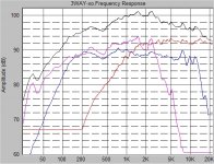
(Btw, I finally got the SPLTrace prog working, the RAW manufs. data is attached - NO crossover yet) Many thanks Omni for your huge effort with the MCA15RCY files!). It looks like this 'beast' might have a 90dB? SPL after xo, as long as the 50Hz SPL P25 response in my box is ok?
If my new MCA15's don't fit into the existing holes, then it looks like M/T in separate boxes on top! Thanks Lots! grant
Although I have much guidance from you to still yet follow-up yet, I was reading in the FRDConsortium of John Krevkosky's 'Transient Perfect XO' tools. I'm just wondering if (I'm sure you have!) any knowledge of this concept and could you *as briefly if possible* please explain it in very laymans terms? I hope its ok to ask!
A VERY basic type answer for me *if possible* would suffice! I truly hope this is ok to ask you?
(Btw, I finally got the SPLTrace prog working, the RAW manufs. data is attached - NO crossover yet) Many thanks Omni for your huge effort with the MCA15RCY files!). It looks like this 'beast' might have a 90dB? SPL after xo, as long as the 50Hz SPL P25 response in my box is ok?
If my new MCA15's don't fit into the existing holes, then it looks like M/T in separate boxes on top! Thanks Lots! grant
Attachments
- Status
- Not open for further replies.
- Home
- Loudspeakers
- Multi-Way
- 3way XO help greatly appreciated!