As an example lets look at midrange highpass
You use 29uF in series and 4.0mH in paralel
In my own speaker I have 68uF and 4.0mH/10ohm, giving a bit lower crosspoint, but not that much different
You will probably find by listening that you could do with the series C only - I have tried it and it sound OK, some would even prefer it
Fact is that the paralel INDUCTOR doesnt do much difference soundvise - actually the benefit from the paralel inducter/resistor mainly is in the upper register
What it does, affects the phase a great deal, and have subtle but important influence on sound - crude ?... I think not, quite the opposite 😉
My ideas are based on practical experience, nothing else and I am not here to have theoretical discussions 🙂
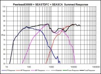
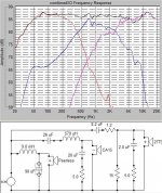
Alright, heres a couple of graphs for your analysis. These are done in Bagbys' crossover designer 5.1. It may take 2 postings, I don't know their sizes...............Question: What is Filter Transfer Function?...........What does it indicate. How does it differ from Response graph in form and function? .............Respectfully.......Omni
Attachments
OK, it's takin 2 posts to get both graphs on here............same questions apply from post above...................By the way Grant.........I need you to figure out what size capacitors to hook up to Frankensteins bolts.....................LOL...............Omni
Attachments
Omni,
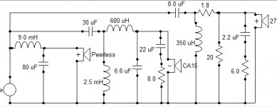
Sorry I can't help you with Mr Bagby's designer, I still haven't used it. But here's my latest xo, with offsets 0, -.75 and 1.5 inches. These are the coils DCR's: (ohms) 9mH 1.2, 2.5mH 0.8, 0.6mH 0.4, 0.35 mH 0.4. The highish 1.2 for the 9mH was a deliberate attempt to get its SPL to better match the CA. The CA 'dip' is now not too bad I think? I'm still trying to refine this xo for you. If we both sim it in SW, we might together come up with something fairly decent.
Re: using Zaph's CA tests, I don't really know....guess it wouldn't hurt to try? Btw, the latest xo values seem a bit peculiar?, but the SW graphs generated from it seem reasonable and the initial broad and deep dip resulting from the new offsets (above) has mostly been
eliminated. best regards, grant
Tinitus, thanks for your input. When I get some spare time I'll try it and let you know the difference (in SW).
Attachments
Omni,
I just noticed the CA response in your 1st and 3rd graphs.
This looks to be unfiltered frd data for this driver? Am I right? The filtered response in my last plot looks very different to your CA graph. Does this make any sense? I have to be careful, so as not to confuse things, as I seem to be error prone lately, lol. grant
Omni,
I can't seem to get into email at the moment, I'm wondering if you had a chance to look at this: www.angelfire.com/electronic/loudspeaker/projects/speakerworkshop.
html
Its pretty good on SW, particularly optimization. grant
I can't seem to get into email at the moment, I'm wondering if you had a chance to look at this: www.angelfire.com/electronic/loudspeaker/projects/speakerworkshop.
html
Its pretty good on SW, particularly optimization. grant
Grant, thanks for the link............I printed the tutorial and again have more to read, and thats cool..........I realize you can't help with Bagbys 5.1, but I think that us simulating in different programs, and comparing notes may be a good way to figure out the glitches,..........Also, I am gonna take your crossover components simulated and run them in 5.1. This will give us a chance to get another perspective.................Tinitus, I was working late last nite, didn't get a chance to post schematic......I will get that up here shortly, and yes, midrange polarity is reversed on those sims..............Respectfully...........Omni
Omni,
I think (cautiously) we're there! Have a look at the attached xo (latest offsets) and response chart.
Maybe its time to crack open a beer to celebrate? This latest xo is as simple as I can get it - it doesn't look too shabby at all! In fact, its slightly smoother than my previous xo with 2 extra coils and a cap! , except for a 1dB greater dip around 6kHz, but that shouldn't be noticible. I decided to pursue my initial idea of least complexity after being encouraged by Tinitus's worthwhile design philosophy of 'keeping it simple' and comment regarding parallel components. Indeed, Tinitus approach in this respect seems to be valid for your drivers individual response.
Anyway, I think this design is worth implementing, i.e., if you are happy with a 9mH DCR=1.2 on the Peerless (this was the lowest inductance I could get, to match the CA). Eagerly awaiting your comments! grant
(I said cautious above, because I haven't considered the impedance etc, just yet) Oops nearly forgot, the tweeter is about 20dB down at Fs, so I think it will be ok.
Attachments
Omni,
I also forgot to mention that with only 2 'standard-values off-the-shelf'
coils, the xo cost should be minimal, and a 1.2 DCR air-core eg Solen,
should be readily available. Unless, of course it needs to be toroidal?
grant
I also forgot to mention that with only 2 'standard-values off-the-shelf'
coils, the xo cost should be minimal, and a 1.2 DCR air-core eg Solen,
should be readily available. Unless, of course it needs to be toroidal?
grant
Hi,
If anyone is reading this and would like to comment on the validity of my last Speaker Workshop simulation, then please do so! I'm after constructive criticism, as I'm still a beginner. To me, *superficially*, it looks great and feasible, but could there be other issues that need to be addressed?
Also, please, if anyone has data/experience with these old Vifa drivers,
P25WO, D75MX and D25TG (for my system), I'd be greatly appreciative! And if I can help you in any way (doubt it, lol) I would.
many thanks, grant
(my D75's are working again, a soldering problem)
Well, very nice BUT I might have misplaced my words
MIDRANGE:
As to the paralel inductor of mids highpass - I did say that you might not HEAR much difference if its there or not - But I also said it is still needed
I think you should try 33uF in series and reinsert paralel inductor with a resistor
AND try a smaller series inductor on lowpass
TWEETER:
Same thing - you still need the paralel inductor with a resistor
Attenuation - try 1.5 ohm
But interesting work😉
hi Tinitus,
you did say previously that you would be very interested to see the results. Would you like me to sim anything for you and send you the results via email? (this assumes you have FRD data for your drivers).
grant
you did say previously that you would be very interested to see the results. Would you like me to sim anything for you and send you the results via email? (this assumes you have FRD data for your drivers).
grant
Thanks Grant, but at the moment I have no project of my own, but I will keep it in mind
I just keep pushing untill theres nothing more to gain, guess it never ends, but thats just me 🙂
I just keep pushing untill theres nothing more to gain, guess it never ends, but thats just me 🙂
sreten said:Hi,
A sensible man when faced with such incoherent and incorrect ramblings gives up.
🙂/sreten.
tinitus said:My ideas are based on practical experience, nothing else and I am not here to have theoretical discussions 🙂
Hi, Well don't indulge in incorrect theorectical ramblings then, 🙂/sreten.
- Status
- Not open for further replies.
- Home
- Loudspeakers
- Multi-Way
- 3way XO help greatly appreciated!