Hi Sreten and Tinitus, many thanks for your comments.
Sreten,
I played for hours with the coil and cap, but no matter what I did, I couldn't get a steep enough acoustic rolloff. Another coil made all the difference. O.2mH was the lowest value that seemed to make a useful difference. Then I attempted to use the network optimiser with appropriate goal, but in this instance had difficulty, so I ended up laboriously changing all the Peerless components systematically by hand. In the end the original coil and cap values seemed the best, all I needed was the extra coil.
Tinitus,
When I get a chance, I'll try the modifications you suggest, and post you with the results.
Thanks to both of you, grant
Sreten, I owe you an apology, i.e. a BIG apology....
I could have sworn that last night the 0.2 mH inductor made a 'slope' difference. I just re-simmed it, because of your question, with and without, and now it makes virtually no difference at all! What was I doing? The only difference it does make, is a very slight reduction in the minor peak at around say 80Hz. ( It was fairly late, and I had been doing it for hours, but that doesn't excuse incompetence! )
*Brilliantly spotted by you, another great insight/correction*. Thank you so much. I really don't know what made me think it made a difference? No idea.
Also I have just received Omni's offsets, Tweeter 0 inches, Mid - 0.75 inches, woofer + 1.5 inches. With the existing xo (now minus the 0.2mH !) this causes a broad dip of nearly 6dB max from below 1kHz right out to 10kHz! Trying to manage this will involve almost an entire xo re-work, so back to the 'drawing board'. This combination of FRD'd drivers is now looking to be a big challenge xo-wise. grant
Tinitus,
Your comment is very much appreciated. Some 'background' information:
Omni and I are both trying to learn Speaker Workshop, with a view to model his drivers response (and compare results) after his lengthy analysis of the FRD tools for his particular situation. He has a slanted (degrees?) trapezoid baffle with the drivers centre aligned vertically. Corrections were applied initially to get a suitable horizontal alignment for the slanted baffle design. Omni gave me the horizontal offsets yesterday: tweeter 0 , mid -0.75, woof +1.5 ..all in inches.
Omni could you please 'chime in' here ?... It would be better coming from you, the designer!
I'm trying to visualise it, but the offsets seem to make sense for a slanted baffle. The woofer V.Coil dimension must be large horizontally. I hope I haven't misrepresented anything so far! If I have, I'm sure/hope Omni will correct me. Thanks Omni!
Tinitus, the problem is, that the revised driver (horizontal) offsets cause a big problem i.e. a broad dip in the overall response IF my last xo circuit is used. Nothing I have done since then seems to fix it, that is, I can't seem to get anything linear. I have briefly tried the SW optimizer but no joy as yet. A big dip around 6kHz. I tried your suggestions too, re: the bass & mid coil, and mid cap but no luck so far.
I know/accept your methodology is tweaking, but in this case I feel a more-or-less linear target response initially is required, then tweaking. Please correct me if I'm wrong. I'm uncertain how to
proceed from here. Your comments are most valued, Tinitus, respectfully, grant
( I should explain a little. Omni has helped me and we have a good rapport, thats why I wanted to try to help him with HIS xo, if I possibly could, because he's been so diligently busy. Besides, it would be in the great spirit of Christmas cheer, to assist a good friend ...).
Its all about learning 😉
I have been looking at your posted simulation - the "dip" as you call it, around 6khz, is merely a slight rise in tweeter response - 3db from 6-12khz, and a bit ressonance below
I would think its driver related and nothing to worry about
I have been looking at your posted simulation - the "dip" as you call it, around 6khz, is merely a slight rise in tweeter response - 3db from 6-12khz, and a bit ressonance below
I would think its driver related and nothing to worry about
I have to laugh at myself here, as I have finally come up with a name for these speakers once they are done...........Frankenstein..........At any rate, here is the clarification on my driver offsets: Considering the tweeter at 0..........The midbass voice coil center is .75 inches BEHIND the tweeter voice coil...........The woofer voice coil center is 1.5 inches AHEAD of the tweeter voice coil...............It appears that I slanted the baffle a bit too much, bringing the Woofer voice coil too far forward, or, taking the tweeter too far back, how ever you want to visualize it........... { It was different on my drawings }.........The midbass voice coil center, being that it is mounted so close to the tweeter, was always gonna be behind the tweeter voice coil center, and that, I can accept..................Problem is, the woofer..........I am a little bummed out about the fact that the woofer voice coil is ahead of the tweeters', but I guess I will have to live with it......................All drivers are vertically centered on the baffle, as you view it from the front............Total baffle height is 47 inches...........Tweeter center is located down 4 inches from the top edge..............Midbass center is at 10 inches down from top edge, which equates to 6 inches from the tweeter............Woofer center is located 34 inches from the top edge of baffle, equating to 13 inches from the bottom edge, which equates to 24 inches from midbass, and 30 inches from the tweeter center..................At any rate, I hope I didn't screw things up too badly, and hope the crossover can correct these problems........I have been diligently working on, and learning the crossover simulation, however, at a slower pace than Grant..............Thank you Grant, very much, for the time you have freely given. And your kind words are greatly appreciated.........................Let's keep in touch................Omni
Hi,
I suppose I should chime in about the offsets.
These should be in relation to the point the phase measurements are made.
That is what is the phase information in the frd file reflecting ?
Does it include the driver coil offset ?
I don't do measurements, but I've always wondered how you
get a reference point for the phase at a measuring distance.
Or is phase set to zero at an arbitary point ?
🙂/sreten.
P.S. Brilliant ? I don't think so, the SLS has an Le of 3.1mH,
putting 0.2mH in series is always going to be fairly pointless.
Sreten, your question beats the **** out of me, as I wouldn't have a clue............ Any way,......... on the driver offsets: When reading the instruction manual, for both Speaker Workshop and Bagbys' 5.1 designer, it is simply stated to enter these figures into the application. They recommend a starting point of 0 for the tweeter, being that it is the driver whose voice coil is closest to the baffle. Jeff Bagby calls this the "Summation Point" and the different driver offsets are set relative to this point..........So that's what I am doing...............I hope to have some legible results to post here soon...................Respectfully...................Omni
Hi, I would like to know what you refer to as voicecoil center
Is it center of first poleplate or buttom of dustcap ?
Is it center of first poleplate or buttom of dustcap ?
Tinitus, The acoustic center, or center of the voice coil, as I have construed it, is the center of the front pole plate or faceplate. I took all my measurements with that as my reference...............In Vance Dickasons Loudspeaker Cookbook, 3rd Edition, there is mention about the botton of the dustcap as being a reasonable reference, Dickason states "However, without using a pulse technique, taking the measurement from the junction of the voice coil and the driven element {cone or dome} will be close enough for good results." HOWEVER......... I read in his 5th Edition, when discussing the driver offset issue on the vertical plane, Dickason described the acoustic or voice coil center as being the center of the front plate. It is with the latter description, from which I decided to proceed, using the center of the front plate as my reference...............I think I see where your head is at on this, and I have a great appreciation for your inquiry. If , for example, I were to consider the dust cap depiction, that would put the midbass acoustic center closer in line with that of the tweeter, because it is definately further ahead on the driver than its' front pole plate...............In the case of the CA15RLY.........it is just about .75 inch ahead of the plate..............So what are your thoughts on this?..........Respectfully.............Omni............Pertaining to your reply about the woofer offset being no problem, and that it might turn out to be an advantage............can you expand on this as well?
Sounds perfect to me 🙂
I guess your offset measurements are to a straight vertical line
Taken that you use center voicecoil/poleplate, I imagine that if converted to dustcab/center you get drivers acoustic center on a curved line
Hope we dont misunderstand each other, I am only trying to get a "picture" of your work
I guess your offset measurements are to a straight vertical line
Taken that you use center voicecoil/poleplate, I imagine that if converted to dustcab/center you get drivers acoustic center on a curved line
Hope we dont misunderstand each other, I am only trying to get a "picture" of your work
Tinitus, you are correct............I used a plumb-bob and dropped a string behind the baffle with the drivers temporarily mounted, and meticulously measured the displacements........Let's keep in touch, as Grant and I continue down the path to crossover heaven ........He's working diligently on this and it is my hope that we can collectively arrive at some cool sounds.............Warm regards.....Omni
Omni,
re: Frankenstein, does that mean you'll be fixing a bolt through the enclosures sides? hehe I needed a good laugh - you made my day!
grant
re: Frankenstein, does that mean you'll be fixing a bolt through the enclosures sides? hehe I needed a good laugh - you made my day!
grant
Omni,
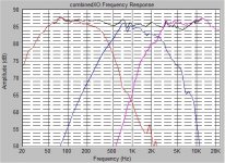
I've been working on the xo to accommodate your offset data, and it seems we're getting there, slowly. The latest graph is attached, it looks almost acceptable now, so the 'frankenstein tag' I'm sure will be inappropriate.
I still haven't figured out how you got the Peerless coil down to 6.4mH,
could you enlighten me please? What DCR did you specify? And how does the response look compared to my attached chart? Just curious.
Btw, my new xo has a 9mH (down from 12) on the Peerless with DCR=1.2 ohms, make it match a little better with the CA. Anyway, its +- 2dB from 50 to 20kHz. Might be ok, you think? best wishes, grant
Attachments
Hi,
Looking better - but you stil have small dips around crossover points - keep working
You should try a resistor on ALL paralel components and adjust them accordingly - I really would like to see the result 🙂
Looking better - but you stil have small dips around crossover points - keep working
You should try a resistor on ALL paralel components and adjust them accordingly - I really would like to see the result 🙂
Hi Tinitus, many thanks
I'm trying to understand your recommendation of a resistor in series with ALL parallel components. So I went back and re-read your previous post: ( format edited only )... quote:
"In my book any paralel component is simply affecting impedance and only there to help the series component to work. Lets take a look at midrange crosscoil - it sees an impedance rise and it has itself an rising impedance with higher frequencies - a paralel condensator drags it down - because of the resistor its possible to use a bigger C, and get a smoother response without the series component, the paralel component would do no or very little to the frequency response, but only affect impedance. Looking at midrange series condensator its the other way round"
Having read this and assuming I have understood you correctly, then maybe, it seems to make sense to me. Thank you! This is a new concept for me. But I would have no idea of what resistance to use. I guess it would be valid to add the resistors in Speaker Workshop, changing the values by trial and error, and see the outcome? I think you don't do simulations, so I'm wondering if in principle its a viable procedure. I don't see why not, because SW sims any type of network.
Would these resistors help to smooth out the dips/peaks at xo points? Or are these mostly from driver response, do you think?
Many thanks Tinitus, I'll try it, and tell you the results. grant
Hi Sreten,
Yes, in hindsight a 0.2mH in series with a 3.1mH 'Le' looks irrelevant.
But you had the foresight to 'see' it. I didn't! So, again, thanks!
grant
Yes, in hindsight a 0.2mH in series with a 3.1mH 'Le' looks irrelevant.
But you had the foresight to 'see' it. I didn't! So, again, thanks!
grant
Sreten,
I hope you don't mind me asking again, but would you have any reference to Zeta's wrt parallel xo's? I don't understand this concept,
and thought incorrectly? it was only applicable to series xo's.
most appreciated... grant
I hope you don't mind me asking again, but would you have any reference to Zeta's wrt parallel xo's? I don't understand this concept,
and thought incorrectly? it was only applicable to series xo's.
most appreciated... grant
Hi,
Zeta's, electrical Q's assuming resitive loads, etc. are all irrelevant.
The filter that you get depends on the acoustic result.
Also see my reply to parallel resistors on crossover parts, generally
its not needed, though I accept its a way of adding a degree of
tunability if adjusting by ear, still its a crude methodology.
🙂/sreten.
- Status
- Not open for further replies.
- Home
- Loudspeakers
- Multi-Way
- 3way XO help greatly appreciated!