Omni,
bonviveur at lycos dot com (funny name, haha) may I please have both sets of files, pre and post FRD tools? For my interest, to see how much difference, but as you know not applicable to my
drivers.
Your comment quote: 'Then, if I need to tweak component values in order to optimize response' leads me to <rant part2> lol.
From my frustration with not understanding the Q-stuff, I emailed Roman B. (rjbaudio.com some great designs if anyone else is reading this) and he ok'd me quoting him here: (thanks Roman!)
To Roman: My question re: 'SW' , please, is this:
If I specify the 'goal' for each driver e.g. 4th order Linkwitz-Riley at an acceptable 'absolute' level i.e. 87dB, the resultant component values bear no resemblance to LR: Q=0.49?
(I'm trying for a 2nd-order electrical here). My quandary is that some of the section Q's are well beyond Butterworth Q's.. Do I need to be concerned that the 'SW' network optimized values exceed Q=0.49?
Roman's reply (he said it's ok to quote him in this thread):
"First I need to know if you processed the manufacturer's data using the FRD tools (Unibox, BDS and FRC) because you have to do this for your crossover simulation to be accurate. The most important step is the generation of minimum phase data using FRC. Then once this data is processed and imported into SW you need to estimate the acoustic centers for each driver relative to the tweeter. Finally when you simulate the crossover you should be more concerned about the phase alignment between the drivers than the type of crossover used. A standard 2nd order acoustic crossover will have decent phase alignment between the drivers "if" the acoustic centers of the drivers are aligned. For a flat baffle the acoustic center of the midrange and woofer are recessed relative to the tweeter. For your case I would estimate driver offsets of 0", -0.3", and -2" for the tweeter, midrange and woofer in
SW respectively. When tweaking the crossover just try to get the best phase alignment between the drivers in and slightly beyond the crossover point using whatever slopes necessary. Textbook crossovers rarely work with real projects".
Omni, by following FRD, well its obvious! The phase stuff is the 'clincher', and the vertical/horizontal displacement. Seems like horizontal can be compensated for in SW. Best phase I assume?, is an abrupt +180/-180 shift around ~ ~2K?
To SW network optimizer. Create 'guess' values, then create a goal maybe LR4, with an absolute response at 300Hz for woofer, maybe ~87dB? Consistent with CA but maybe including BPG? don't know.Tweeter response will be higher, so ok. Use maybe 500 points, more if u have a faster PC. Then use the optimizer on the
goal. Voila, new values, lol. This has to be done on individual networks for each driver. It wont work on a combined network. Combine them later. Then tweak components as required. The links at the end of the SW doco explain this better. But this should get you started, its pretty easy (especially for a graphic artist!
like yourself, well versed in s'ware)....grant (I want the DIYaudio verbiage award!)
Tinitus, Hi!
I've been re-reading your tweaking methodology again, and find it very enlightening.
Its very interesting to me that cap/coil values can be changed 'on the fly' with no repercussions, so to speak, to so called 'theory'!
This is an insight to me, thank you very much.
It makes me wonder yet again what all the 'fuss is about' regarding all the so called differences in crossover types is! thanks Tinitus.
I guess if what you hear is good, then thats the best crossover! grant
Hi,
Now dont loose the grip, believe in what you do, but I know your frustration
I think you got the point - simulation or not, at some point you have to build and listen - use the cheapest compoinents, you might not be satisfied right away
And no, I dont believe any filter sound good, straight response or not - remember theres a lot of compromises in a speaker, its a winn and loose game, sort of
I have been very lucky to learn from a very skilled person, and he uses advanced measurements only - I admit, you can get a long way with measurements/simulation, its not just good enough in my world - he really dont like when I "cheat" and dont follow "textbook" theory
Resistor on paralel component is in series with the paralel component
I like it because it gives possibility of adjustment
In my book any paralel component is simply affecting impedance and only there to help the series component to work
Lets take a look at midrange crosscoil - it sees an impedance rise and it has itself an rising impedance with higher frequencies - a paralel condensator drags it down - because of the resistor its possible to use a bigger C, and get a smoother response
without the series component, the paralel component would do no or very little to the frequency response, but only affect impedance
Looking at midrange series condensator its the other way round
The response curve can be looked a bit like a plastic bag filled with water - when you press down at a point, it goes up somewhere else, and down again, and when you slap it hard you get movement, so its a matter of touching it soft and gently - as in life I dont believe in brute force
A skilled person once said that the less components the better sound - its a matter of just enough, no less no more - I should mention that he used a lot, often too much
Hey all......I greatly enjoyed your comments and will proceed per your influences..............I read another tutorial on SW and it appears that the program makes the changes for you as you set the targets? I have a beginning foundation to start with, so will proceed slowly, perhaps this afternoon.....................Grant I will be attempting to send you the files, here shortly after I finish checking mail and determining how to package these babies. There are a LOT of files created and hopefully the way I named them will be self explanatory......If not, contact me............I may ZIP them up................do you have an unzipper?.......At any rate, I will post here, to check it out if you have any problems opening them up or finding..............All I ask is that you keep me posted as to your progress and results.................Tinitus, I will continue to post progress, here, and look forward to your correspondence.............Respectfully..............Omni
Tinitus,
Thank you for your very detailed reply, much appreciated. I like your plastic bag analogy.
Omni,
I unzipped all the 32! files and emailed you from my main address, as I am unfortunately unsure of which ones to use. I'll certainly keep you posted.
Best regards to you both, grant
Thank you for your very detailed reply, much appreciated. I like your plastic bag analogy.
Omni,
I unzipped all the 32! files and emailed you from my main address, as I am unfortunately unsure of which ones to use. I'll certainly keep you posted.
Best regards to you both, grant
tinitus said:
In my book any paralel component is simply affecting impedance
and only there to help the series component to work
Hi,
Simply put, this not true.
Presumably you are refererring to second order parallel electrical
networks, in this case your "model" makes some sense but it
certainly is not as simple as you state, as the the overall Q of
the electrical filter is a variable, though I guess you think that
the series resistor determines that, perhaps, but maximum Q
is determined by the ratio of the inductance and capacitance.
As far as I'm concerned tweaking ear is fine, and actually understanding
electrically / acoustically whats going on is also fine too, both methods
are limited on their own, in the end measurements tell some of the truth.
🙂/sreten.
grantnsw said:
These comments lead me to to believe that you just trust SW!
Change values as you like 'willy-nilly' (keeping the total response
graph open on screen) and bingo - there's the output.
No needto worry about, in our case, various 2nd order filter types.
Why then all the fuss is made about various Q's, offset
sensitivity, differing group delay etc etc, is beyond me!
Hi,
Trusting anything implicitly is not a good idea.
But you are essentialy correct in that most talk about crossovers
in terms of an electrical network, e.g. one component = first order,
two = second order, and their behaviour, is completely misguided.
The issue that is relevant is the final acoustic behaviour, and making
this conform to a classic alignment is far more difficult that it appears.
e.g. check this out for another (but completely different) 2nd order
L/R acoustic response and compare the c/o to the previous example.
http://www.zaphaudio.com/ZD5.html
Again the Q is ~0.5, again the question is what Q ?
🙂/sreten.
I guess I should have said; "...simply put...", instead of; "...simply is..." 😉
Anyway, in this nothing is simple....what do they say..." the simplest things are often the most difficult"
Anyway, in this nothing is simple....what do they say..." the simplest things are often the most difficult"
Omni,
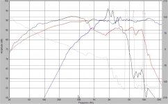
I thought your XO details belong here, as we work through it. The FIRST graph is your drivers only, after the FRD tools, no XO, in phase. There's some interesting things to note:
* Peerless: understandably good bass extension and classic cone break-up at 2kHz, high sensitivity,
* CA15: Extended response, reduced sensitivity, dip from 700 to 1700Hz. Interestingly, Roman B's Calypso design showed a smaller dip at 1400Hz.
* 27TDFC: fairly smooth, resonance low at 550Hz.
( My comments below are from a beginners perspective, and when (not if!) I make blunders or oversimplifications, I hope someone corrects me ).
The overall system SPL will of course be determined by the CA which shouldn't need any attenuation or maybe very little. I still don't know if Speaker Workshop includes Bandpass gain, so we may get another 2dB for the CA? A target goal of a 4th order acoustic response for each network section might do the trick, as an initial choice anyway, for say around 87dB I hope!
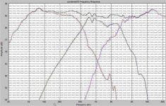
The SECOND graph is my first brief attempt at a full 2nd Order design, Mid polarity inverted. The tweeter xo still needs some work (it was getting late), and offsets for all drivers was '0' inches.
I did get a slightly better response from other values, but forgot to save it. So there may be more than one way of getting an acceptable result, prior to tweaking. The best sounding may be
different again. At +- 2dB its possibly ok, I'll try for smoother when I get your measured offsets.
The tweeter Fs at 550 is way down, so it might just be possible to go all 1st order except for the Peerless, and assuming the CA off axis is still acceptable out to around 4kHz. The TDFC even if crossed at 2200Hz, 1st order electrical should be down around -27dB assuming 6dB LPad and driver rolloff. Its worth simming anyway. grant
I thought your XO details belong here, as we work through it. The FIRST graph is your drivers only, after the FRD tools, no XO, in phase. There's some interesting things to note:
* Peerless: understandably good bass extension and classic cone break-up at 2kHz, high sensitivity,
* CA15: Extended response, reduced sensitivity, dip from 700 to 1700Hz. Interestingly, Roman B's Calypso design showed a smaller dip at 1400Hz.
* 27TDFC: fairly smooth, resonance low at 550Hz.
( My comments below are from a beginners perspective, and when (not if!) I make blunders or oversimplifications, I hope someone corrects me ).
The overall system SPL will of course be determined by the CA which shouldn't need any attenuation or maybe very little. I still don't know if Speaker Workshop includes Bandpass gain, so we may get another 2dB for the CA? A target goal of a 4th order acoustic response for each network section might do the trick, as an initial choice anyway, for say around 87dB I hope!
The SECOND graph is my first brief attempt at a full 2nd Order design, Mid polarity inverted. The tweeter xo still needs some work (it was getting late), and offsets for all drivers was '0' inches.
I did get a slightly better response from other values, but forgot to save it. So there may be more than one way of getting an acceptable result, prior to tweaking. The best sounding may be
different again. At +- 2dB its possibly ok, I'll try for smoother when I get your measured offsets.
The tweeter Fs at 550 is way down, so it might just be possible to go all 1st order except for the Peerless, and assuming the CA off axis is still acceptable out to around 4kHz. The TDFC even if crossed at 2200Hz, 1st order electrical should be down around -27dB assuming 6dB LPad and driver rolloff. Its worth simming anyway. grant
Attachments
Hi Sreten,
Many thanks for your comments, I had thought that many of my questions were(still are?) too inept. I do think I understand the electrical/acoustic distinction now, but am still sometimes guilty of just sometimes specifying electrical.
I did re-read your previous link to Zaph's waveguide, (still pondering) and will revisit the ZD5 so that I might 'get my head around it'!
As Omni has been very busy with the FRD tools and painting etc, I offered to do simplistic SW sims for him so we could both learn. If you have any input on this, including my last few posts, it would be, as usual, very much appreciated. Thanks, grant
Hi,
If anyone of any skill level is reading this topic and is considering submitting a question, comment, helpfull advice or to share a design, then please do. (Especially if you have experience with Speaker Workshop). You would be very welcome! I personally maybe can't answer questions but other more qualified people here might like to. There's 4 of us here, but nearly 4000 page views! Thanks, grant
If anyone of any skill level is reading this topic and is considering submitting a question, comment, helpfull advice or to share a design, then please do. (Especially if you have experience with Speaker Workshop). You would be very welcome! I personally maybe can't answer questions but other more qualified people here might like to. There's 4 of us here, but nearly 4000 page views! Thanks, grant
Sreten,
Hi, Re: this 'quote':
"e.g. check this out for another (but completely different) 2nd order
L/R acoustic response and compare the c/o to the previous example.
http://www.zaphaudio.com/ZD5.html Again the Q is ~0.5, again the question is what Q ?"
Your reference to the ZD5 xo is postgrad stuff, well beyond XO's 101!
Help! I'm having trouble understanding your reference to Zaph's waveguide let alone this one! and your repeated 'what Q'. Please give me some direction here? I've forgotten all my ancient filter mathematics 3 decades ago! ....respectfully! grant
Hi,
If the acoustic response follows moreless a L/R response in the c/o
region and the acoustic phase (including offset) is near 90 degrees
at - 6dB for both drivers at the same frequency point then you will
have a near 2nd order L/R acoustic crossover with Q near 0.5.
Nothing to do with Zeta of the crossover components.
🙂/sreten.
Hi Sreten, thank you!
Would you know of a good reference text (preferably in laymans terms) descibing your filter theory? I'm having trouble understanding all this. E.g., I had heard the term Zeta before, but I thought it was relevant only to series xo's. You must have learnt all this at University
so there must be a reference somewhere. I don't want to keep bothering you if I'm 'out of my depth'. If I can understand the mathematics, then I can learn and then maybe ask you considered questions. Many thanks, grant
Hi,
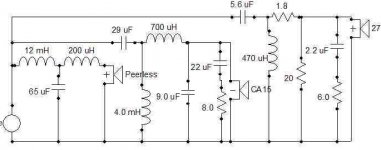
If anyone else is interested, this is my latest xo for Omni's drivers,
including specified Zobels on mid and tweeter. I'm not sure if its a good
idea to show it, because of my lack of knowledge, but for what its worth here goes... (the response looks acceptable if anyone wants to SW sim it), but its based on '0' horizontal offsets for all drivers. grant
(any comments highly appreciated)
Attachments
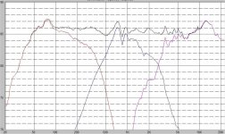
I forgot to mention that to 'a trained eye' it might look ridiculous!
But, hey you've got to start somewhere, and this is the flattest response I could get from SW given the FRD'd data, and constraints.
Please feel free to comment on its viability, or tell me if its garbage!
grant
But, hey you've got to start somewhere, and this is the flattest response I could get from SW given the FRD'd data, and constraints.
Please feel free to comment on its viability, or tell me if its garbage!
grant
grantnsw said:Hi,
If anyone else is interested, this is my latest xo for Omni's drivers,
including specified Zobels on mid and tweeter. I'm not sure if its a good
idea to show it, because of my lack of knowledge, but for what its worth here goes... (the response looks acceptable if anyone wants to SW sim it), but its based on '0' horizontal offsets for all drivers. grant
(any comments highly appreciated)
Hi, I don't understand the 200uH on the Peerless, 🙂/sreten.
Hi,
seems you have a bit of "dips" around crossoverpoints
12mH on bass could be too big
29uF on mid a bit small
0.7mH om mid maybe a tad too big
tweeter slope has a bit of ripple - might help with a resistor on 0.47mH (in that case 0.47mH might need adjustment)
But you might be close, and only listening can tell
- Status
- Not open for further replies.
- Home
- Loudspeakers
- Multi-Way
- 3way XO help greatly appreciated!