Hi all, I'm trying really hard to work out how to wire the reset 'pin' on the 3E TPA3255 board? - could anyone tell me how to use this if I need to reset? It doesn't have a physical switch so how would I go about resetting the board? I've searched but the more I search the more it seems to be some sort of hidden mystery. I just need to know how you wire it/get it to reset if I need to use it?????????
http://www.3e-audio.com/wp-content/uploads/2018/07/DS_EAUMT-0260-2-A_Rev1.0.pdf
See page 6
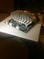
take a picture bottom side your amp?
See page 6
take a picture bottom side your amp?
Hi all, I'm trying really hard to work out how to wire the reset 'pin' on the 3E TPA3255 board? - could anyone tell me how to use this if I need to reset? It doesn't have a physical switch so how would I go about resetting the board? I've searched but the more I search the more it seems to be some sort of hidden mystery. I just need to know how you wire it/get it to reset if I need to use it?????????
Looking at DrMordor's pdf file it looks like the reset pin is brought out to a single row connector at the edge of the board. All you should need is a SPST momentary push button between the reset pin and ground.
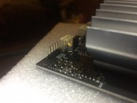
Ah ok that makes sense i think (I'm a beginner at all this!). So the reset pin and the grd pin in the photo?
Looks like it. The PDF appears to suggest it... so go for it.
You will need a connector some wire and a switch.
For the first test just take a mid-value resistor, 2.2k, 4.7k something like that and touch the wires across the two pins... see what happens. If you don't get an immediate lesson in using fire extinguishers, it should be okay.
The thing is that when you let all the smoke out, electronic devices tend to stop working....
From your other thread, asking about my standby switch drawing, the simple resistor test will tell you if that will work as well... it should be silent as long as reset is held low (i,e, grounded). So long as the 12volts, which is also brought out to a board edge connector, stays on you've got all you need to make that work as well.
Spec sheets are our friends....
Last edited:
Well I did a test on my table (wires everywhere to the horror of my other half). For the most part very happy - it worked! The reset worked when I connected a wire across the terminals it all went nicely silent which was good, so thanks for your input on that, and as the reset carries 3.25v if I get a LED and wire in as per your diagram this should work as the LED will go off when in reset (low/standby) as when reset grounded there is no voltage from the reset pin which will work nicely for me to see whether or not it is in reset (LED off) or in high/working (LED on). Shame it is only 3.25v as the light will probably be a little dull as the led has to shine through a green bulb lens on my chassis (I was hoping to use the 12v outlet on the board but this has 12v running to it whether or not it is in standby or not which doesn't help.
My only issue so far (besides one channel not seeming to play as much bass as the other but that is probably my temporary wiring skills so will worry about that later) is the volume pot - I bought a cheap 10K logarithmic pot from ebay to experiment which didn't go to well - on low/off volume it still played at the level you might read a book to while having music on quietly in the background. On turning it up the volume increased a lot at the beginning of the turn then didn't increase much as I turned further before getting to max volume which was only just at the highest volume I would play music at when playing loud music. Did I get the wrong pot? A linear would be better? Would a 25k or 100k be better to try (In my very very limited guess work a 100k would be less loud at full volume?) Trying to avoid anything more complicated than a simple pot.
My only issue so far (besides one channel not seeming to play as much bass as the other but that is probably my temporary wiring skills so will worry about that later) is the volume pot - I bought a cheap 10K logarithmic pot from ebay to experiment which didn't go to well - on low/off volume it still played at the level you might read a book to while having music on quietly in the background. On turning it up the volume increased a lot at the beginning of the turn then didn't increase much as I turned further before getting to max volume which was only just at the highest volume I would play music at when playing loud music. Did I get the wrong pot? A linear would be better? Would a 25k or 100k be better to try (In my very very limited guess work a 100k would be less loud at full volume?) Trying to avoid anything more complicated than a simple pot.
and as the reset carries 3.25v if I get a LED and wire in as per your diagram this should work as the LED will go off when in reset (low/standby) as when reset grounded there is no voltage from the reset pin which will work nicely for me to see whether or not it is in reset (LED off) or in high/working (LED on).
I'd be careful with that... the reset is an input, you don't want to draw current from it. As luck tends to go the LED could/would draw just enough current to make the reset unstable causing sporadic shutdowns and start ups.
It is better to follow my original plan using a SPDT switch and the +12 helper supply to alternately ground the ON led or the reset...
On turning it up the volume increased a lot at the beginning of the turn then didn't increase much as I turned further before getting to max volume which was only just at the highest volume I would play music at when playing loud music. Did I get the wrong pot? A linear would be better?
The outputs of the 3255 are BTL (Bridge Tied Load) which means you have two amplifiers operating out of phase to get the full power.
According to the PDF that amplifier needs a balanced input, so you may have to look into adding a pre-amplifier and phase splitter circuit to get full power. These don't need to be especially complex, a couple of op-amps and a couple of transistors, with a palm full of passive parts will do the job, but it's clearly not "my first amp" stuff.
Ah ha, I get the reset idea - I was struggling with it as I said but hadn't realised the wiring of the switch has the ground on one side and either reset or 12v on the other- yep I see how that works now rather than just reset and ground as I had.
The volume pot is disappointing as I thought I was almost there with it - hoped to avoid a pre amp much less make one! Main problem I've made a chassis with volume pot (it's made to look like a vintage box, rusted up a bit, with old voltmeter and ammeter (not wired up) with old hotrod panel bulb etc which has just been my enjoyable project as I like the old stuff) but now have a big chicken head volume knob thats in danger of being redundant! Would a simple passive balanced pre amp that's cheap do the trick or would I need to avoid the cheap stuff?
The volume pot is disappointing as I thought I was almost there with it - hoped to avoid a pre amp much less make one! Main problem I've made a chassis with volume pot (it's made to look like a vintage box, rusted up a bit, with old voltmeter and ammeter (not wired up) with old hotrod panel bulb etc which has just been my enjoyable project as I like the old stuff) but now have a big chicken head volume knob thats in danger of being redundant! Would a simple passive balanced pre amp that's cheap do the trick or would I need to avoid the cheap stuff?
Ah ha, I get the reset idea - I was struggling with it as I said but hadn't realised the wiring of the switch has the ground on one side and either reset or 12v on the other- yep I see how that works now rather than just reset and ground as I had.
The volume pot is disappointing as I thought I was almost there with it - hoped to avoid a pre amp much less make one! Main problem I've made a chassis with volume pot (it's made to look like a vintage box, rusted up a bit, with old voltmeter and ammeter (not wired up) with old hotrod panel bulb etc which has just been my enjoyable project as I like the old stuff) but now have a big chicken head volume knob thats in danger of being redundant! Would a simple passive balanced pre amp that's cheap do the trick or would I need to avoid the cheap stuff?
Any pre-amp for this board will likely need to be custom designed, built and tested. That's not as daunting as it sounds but you will need test gear the average DIY guy doesn't have, in particular a dual channel oscilloscope and a signal generator. In the end it will likely be a smallish board, maybe 2 inches square, designed specifically do drive that module.
Again I will confess to a lack of experience with this particualar board.
Lets see if anyone else wants to chime in...
Last edited:
Yea, that's me hitting a brick wall at the moment. I really appreciate the help you've given me Doug. Guess I could always just use source (laptop) for volume but that sucks. Anyone?
Even as this amp has a balanced input, you can still use it single ended, when you put - negative in to ground.
Then, your pot should work, but as it is a logarithmic (can´t use linear here!) one, you can use it the wrong way.
One side to ground, the other to the source and the middle to the amp input.
That should work. If behaves erratic, change source and ground.
An alternative could be a single ended to balanced buffer after the pot. Will work fine if your source has a strong, low impedance output, like a CD player.
If not, for high impedance sources, use a single ended buffer in front of the pot. As far as I know the 3E-amps even have some voltage output on board.
If you buy these buffers at eBay, might cost you 12$ for small, finished boards.
Only problem, you have to know what you do. If you wire this stuff up wrong, you will get terrible hum.
Yea, that's me hitting a brick wall at the moment. I really appreciate the help you've given me Doug. Guess I could always just use source (laptop) for volume but that sucks. Anyone?
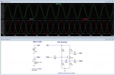
It can be extremely simple, as the thumbnail shows...
That's 4 resistors, 4 caps, 1 transistor ... it could be built about the size of a postage stamp on perfboard and would cost about $3.00 to build. You will, of course, need 2 for stereo.
What it does is take the single ended signal from your volume control and convert it into a balanced signal for the module. VLeft goes to the + input, VRight goes to the - input... easy peasy.
Attachments
Last edited:
An externally hosted image should be here but it was not working when we last tested it.
BTL board was bought from taobao. It sounds much better.
Shared album - david leung - Google Photos
Also, The four 1000uf capacitors
Shared album - david leung - Google Photos
I have the 3e 3255 stereo amp. Jumpers used to select SE or balances input.
I have a passive preamp....dact type volume control and an input select. Works great.
I have a passive preamp....dact type volume control and an input select. Works great.
I have the 3e 3255 stereo amp. Jumpers used to select SE or balances input.
I have a passive preamp....dact type volume control and an input select. Works great.
Thanks for that ... I missed it... The PDF doesn't describe this feature, but it is shown on the board picture... so moving a jumper solves the problem. I like that.
One more issue ... the overall gain ...
The PDF specifies 20db, that's a voltage ratio of about 10 to 1
The output is specified as 185 watts on 8 ohms... That's about 38 volts on the speaker.
BTL doubles speaker voltage so... 19 volts.
So... it would take 1.9 volts of input to reach full output.
That's a pro-audio level signal. I don't know if that will be an issue here or not...
Attachments

Last edited:
Solved it - set it all up again and after playing with it I got the volume control working perfectly (I think). All wiring as Turbowatch stated - not sure what I did yesterday but perfect today. High volume not quite as good as I would like but thats because I run my music from the jack on my macbook so not enough voltage. Hopefully I can start building it (just got to wait for my STDP switch) and I'm there. Will post a pic if I get it finished. Thanks for all your help.
- Home
- Amplifiers
- Class D
- 3E audio board reset