hey pelanj - did you get to listen to the effects of your 8PE21 phase corrector? - if it seems pretty much optimal , maybe you could post the model for printing.
Hi Freddi, I did not listen to it (I do not have a proper box, just the back cover at the moment), but measurements in post #47 show it seems to work quite fine. I will post the model today. I will also update the first post with index.
Here are some measurements of the 8PE21 with and without the phase corrector (or how to call it) - at the same angles. The back of the driver was inside the small cover shown in this thread.
With and without were measured at exactly the same position, the third picture compares the measurements on axis and at a relatively large angle off axis (more than 45 deg IIRC). Everything is heavily smoothed to see the trends.
Wow, that's quite nice!
Obviously it rolls off the highs to a degree, but the polars are much more conistent. And the high frequency rolloff can be a GOOD thing, because a $5 waveguide is cheaper than a $10 inductor.
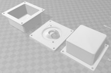
Another teaser - flange and cover for Visaton FRS5X to be used as midrange on synergy horns. Test print made, it needs some small improvements for better mechanical fit (increase tolerances on the flange). Today I will measure to see if this is suitable or not.
Attachments
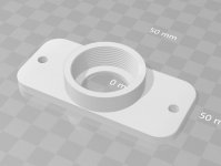
And for the screw-in drivers, I made a small adapter. Be warned though, it fits my no name drivers (it is a 1.375-18 UNEF thread) but it does not fit e.g. EV DH-3).
Nice work
Can you make a file with 1-3/8” threads ?
If you can provide exact name of the thread and it is included with Fusion 360, then yes. 1-3/8" should be equal to 1.375" - but maybe it is another standard than UNEF I used.
If you can provide exact name of the thread and it is included with Fusion 360, then yes. 1-3/8" should be equal to 1.375" - but maybe it is another standard than UNEF I used.
I will find the info for you tomorrow
Thank you very much
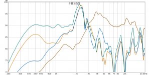
Here are some measurements of the FRS5X, relatively nearfield (ca 25 cm). Only gated, no smoothing.
Brown - free air
Blue - on flange, without back cover
Orange - on flange, with back cover
Green - on flange, with back cover and on corrugated cardboard baffle ca 20 x 25 cm
I wonder where the resonance at 2.3 k comes from - maybe from the front chamber as a Helmholtz resonator? I guess one could get rid of it by attaching it to the wall of the horn - then the "port" is longer and will be tuned lower if I am correct.
Attachments
hey pelanj - I'd like to see a print. file for little Karlson suitable to have a mid-tweet using 3FE22. It could be just the front chamber and enough surface to mount the driver. Maybe a 20 degree angle for its baffle - ?
Hi Pelanj,
please upload the iges or step or other format that can be opened in Catia for FRS5X flange. I want to change it a little before printing and testing.
Thanks!
please upload the iges or step or other format that can be opened in Catia for FRS5X flange. I want to change it a little before printing and testing.
Thanks!
Freddi, would you make a hand drawn sketch with dimensions? Then I can have a look at it.
Arcgotic, will do later today.
Arcgotic, will do later today.
hi pelanj - a rough idea - feel free to improve it - make it more practical
https://i.imgur.com/3IPAW6K.jpg
the cardboard lens -chamber worked well but was for a "phenolic ring tweeter" so somewhat smaller.
wonder how much back chamber 3fe22 would need to work down to say 350Hz?
https://i.imgur.com/3IPAW6K.jpg
the cardboard lens -chamber worked well but was for a "phenolic ring tweeter" so somewhat smaller.
wonder how much back chamber 3fe22 would need to work down to say 350Hz?
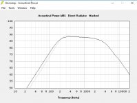
Ok, I get the idea. I need to make a 3D model of a flange attachment for the 3FE22 anyway for my AMT Synergy project. The 3FE22 is a really nice driver, worth exploring a 3D printed Klam or Rocket style speaker (on my to do list now🙂. Hornresp says 0.5 l is good (dark line), 0.3 l seems to be fine as well (grey). So a small 8 x 8 x 8 cm cube should be fine.
I actually also thought about making a K-Slot for the 8PE21 as the "phase cover". On my list as well🙂
Arcgotic, see the attached STEP file in the ZIP. The fit of the driver is a bit tighter than I like, so it needs to shave a few tenths off around the gasket.
I actually also thought about making a K-Slot for the 8PE21 as the "phase cover". On my list as well🙂
Arcgotic, see the attached STEP file in the ZIP. The fit of the driver is a bit tighter than I like, so it needs to shave a few tenths off around the gasket.
Attachments
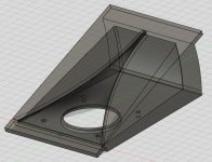
So this is a quick try. To make it printable in one piece and with little support, the mounting flange is only on top and bottom. I see this enclosed in a rectangular box made of max 15 mm thick material. The hole for the 3FE22 is most probably not completely correct, the gasket will be pressed a bit as I made only a 3 mm recess and I think it was actually higher - and I am not at home to measure.
It needs some tuning, therefore the STL file is only for the purpose of viewing or for experimenters to print - nothing was double checked on it, nor did I have a chance to print it myself yet.
It needs some tuning, therefore the STL file is only for the purpose of viewing or for experimenters to print - nothing was double checked on it, nor did I have a chance to print it myself yet.
Attachments
So this is a quick try. To make it printable in one piece and with little support, the mounting flange is only on top and bottom. I see this enclosed in a rectangular box made of max 15 mm thick material. The hole for the 3FE22 is most probably not completely correct, the gasket will be pressed a bit as I made only a 3 mm recess and I think it was actually higher - and I am not at home to measure.
It needs some tuning, therefore the STL file is only for the purpose of viewing or for experimenters to print - nothing was double checked on it, nor did I have a chance to print it myself yet.
How large is this print? In inch
It is roughly 4 x 8 x 3 inches - for details, please check the STL file. The units of the files I post are always mm.
Cool! so around 160mm internal chamber height? - wonder how the chamber depth effects the response from this angle (20) to say 15 degrees?
I'll ask for a printing quote - don't have a 3FE22 but hope to get one.
Do you think the JBL style slot scaled would do better with 3FE22 than the K-cavity/slot?
I'll ask for a printing quote - don't have a 3FE22 but hope to get one.
Do you think the JBL style slot scaled would do better with 3FE22 than the K-cavity/slot?
Last edited:
- Home
- Loudspeakers
- Multi-Way
- 3D printed audio stuff (with STL files)