I had zero warp when I smeared the lowest layer a bit - where it did not matter. I also increased the speed a bit lately, so maybe that is why.
Another trick is to use 50:50 pva glue mixed with water. Paint that onto the glass plate and bake it dry before printing. Print sticks and doesn’t lift off until you take a razor blade to it.
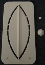
The "eye" layer is printed. It did not warp. I used Hilbert curve infill and that might have some influence as well - the rectilinear pattern shrinks in the two major direction lifting the corners. I got the side edges slightly concave, which does not matter at all.
I see a little design issue - there should be more screw holes around, at least a pair in the middle of the long side.
I see a little design issue - there should be more screw holes around, at least a pair in the middle of the long side.
Attachments
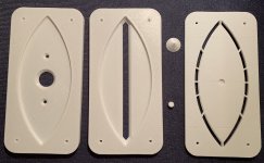
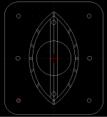
So here is are the STLs - the cone and joint are meant to be glued to the eye plate. The coverage angle is calculated as ca 51 degrees by Patrick Bateman's Paraline calculator. It is an easy print and with 0.2 mm layer it came out really nicely. I would like to try a "synergized" paraline - maybe it will even fit this one - only a new driver plate would have to be printed. The slot and eye plates will be glued together, but the driver plate needs to stay removable anyway.
Attachments
Great work ! - hey pelanj for the double slot tube and mini-klam, a printing service wants to know:
What is the layer height? Also What is the wall thickness? Infill?
What is the layer height? Also What is the wall thickness? Infill?
I printed almost everything with 0.2 mm layer height, 3 layers of wall thickness and 20 % infill.
Pelanj,The coverage angle is calculated as ca 51 degrees by Patrick Bateman's Paraline calculator.
Nice prints!
From an eyeball inspection of the "eye", looks narrower than 51 degrees vertical dispersion to me. Do you have a link to Patrick Bateman's Paraline calculator ?
Art
with 0.2 mm layer height, 3 layers of wall thickness about how thick are the finished double slot tube and mini-Klam walls? (I'm not one bit familiar with 3D printing)
Art, I found it here: ~ Sunshine ~ - it should have the correct A and D dimensions, but I used a three point circle through these, so it is not a true parabola as it should be if I am correct.
Freddi, this information should be sufficient for the printing service. The resulting wall thickness is (with my 0.4 mm nozzle) 1.2 mm horizontally and 0.6 mm vertically with the infill inbetween. If I remember correctly, the mounting plate is 5 mm thick in total and the tube walls 3 mm in total. If you specify 3 layer wall thickness, you should be fine.
Freddi, this information should be sufficient for the printing service. The resulting wall thickness is (with my 0.4 mm nozzle) 1.2 mm horizontally and 0.6 mm vertically with the infill inbetween. If I remember correctly, the mounting plate is 5 mm thick in total and the tube walls 3 mm in total. If you specify 3 layer wall thickness, you should be fine.
You mean coupling two 2" exit drivers together with two paralines above each other? If you define the thickness, A1 and D1 and mounting pattern, I can make a 3D model quite fast - in the same style as the small one. I guess it will be pretty large and it would need external support made out of wood to hold the weight of the drivers. And if you make a hand drawn sketch, it would be even easier.
I really meant 2- 2" cd in 1 len but that doesn't work. How about one make for 2" exit, a=30 d=60 same thickness, basically half of yours.
Did you mean 120 mm slot length and 60 mm eye total width or opposite ratio? For which driver? So that I get the bolt pattern right. I should have some time to waste next week, so I might do it as an exercise🙂
Have you try any tube with a dome tweeter such as Tymphany ne19? What do you think about it ?here is my collection of K-tubes
No, I still need to buy a pair. I think you could use Patrick Bateman's adaptor with the K-tubes posted. Did you see Don VK's simulations? I think that the tubes do not need a compression driver to work.
hey pelanj, maybe make a mid/tweeter module with 8pe21 and compression driver on the dual slot K-tube. If 8pe21 has enough on-axis rise then maybe a JBL style lens
rough pattern: https://i.imgur.com/E3MneZr.jpg
1hiep0 - K-tubes have been used with car coax such as 5 inch and 6.25" Polk with center mounted dome tweeters in Karlson style klams.
https://i.imgur.com/OiXOmeU.jpg
https://i.imgur.com/ecoPQ0b.jpg
This interesting oddball has a short K-tube https://i.imgur.com/6nWYJgm.jpg
Last edited:
Freddi, that JBL style lens is a good idea, I will try that.
Now when we know what the K-tube does, the small one aiming up and placed close to the floor makes perfect sense to me🙂
Now when we know what the K-tube does, the small one aiming up and placed close to the floor makes perfect sense to me🙂
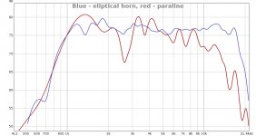
I am not sure if I got the paraline right. I checked the 3 point circle vs a parabola and for these dimensions, the circle is close enough with very minor differences. But the mouth should have been 5 mm wider, now I think I finally understand the spreadsheet. The picture compares the FR in my quick-and-dirty in-room style measurement the same driver (Beyma CP385Nd) in a small eliptical exponential horn (blue) and the paraline. There are some dips at 2.6, 3.7, 6.0 and 7.4 kHz that can be seen as negative group delay in the GD curve. I wonder if one could get rid of these somehow, I am going to try to fill the area below the driver plate by polyfil and compare.
Attachments
- Home
- Loudspeakers
- Multi-Way
- 3D printed audio stuff (with STL files)