Dear Mr. Minhaj
Big Hum, Microphony !! Arrh! why my 5814a and 6080 is very quiet. Even my 6SN7 x 4 Preamp is also very quiet.
so it is worsen than my 2 HP amps if it has big hum and microphony.
Even I my very old integrated amp Aiwa XA-007 use network resistors for headphone output still very quiet and sound so fun.
This Headphone amp is more difficult for me than my 4P1L PP 10 watts that I made. It sounds ok to me too may be use network resistor instead on 4P1L PP will sound better b/c no hum.
PS. I revised it again
Attachments

.1 amp is 100 ma, .01amp is 10ma -check your calculation.
DHT sound is best sound, like everything in life, it is hardest to implement, tube or transistor whatever.
4P1L PP should sound very good if it only sound ok then something is not right, may be not implemented correctly may speaker mismatch. In triode mode it should give you 4/5watt you run it in pentode ur ul?
Regards
Oh Thank you Mr. Minhaj. my wrong calculation
the correct is 0.01 so 0.01 * 2600 = 26VDC + 102 VDC = 128VDC B+
4P1L PP vocal is just ok but bass is huge!! I prefer 45 SE of my acquaintance. Voice is very good.
Next step need to design 3.7VDC regulated supply. I might go to power supply section in this forum maybe someone had designed 3.7VDC 440mA (220mAx2)
Question is why they use 3.7VDC - 2.3VDC at filament? instead of 1.4VDC
I guess it will deduct 102VDC - 2.3VDC = 99.7VDC as tube datasheet.
the correct is 0.01 so 0.01 * 2600 = 26VDC + 102 VDC = 128VDC B+
......+5 volt for tube variation
I might go to power supply section in this forum maybe someone had designed 3.7VDC 440mA (220mAx2)
......you need 2x filament supply, one for right channel one for left channel. Since filament is the cathode otherwise crosstalk will happen.
Question is why they use 3.7VDC - 2.3VDC at filament? instead of 1.4VDC. I guess it will deduct 102VDC - 2.3VDC = 99.7VDC as tube datasheet.
......No. 3.7 volt is bias voltage, 3.7-2.3=1.4 volt is filament voltage. Explanation and calculation available at Bartola's site.
Thank you very much for sharing valueble knowledge of 3A5 HP AMP. There is a long way to search information to get 104vdc B+. I will try to search small HV Regulated in web.
Once I found, I will share to this topic again. Need to search for compact size. Chinese 6z4 6p1 is so large may be I can find smaller.
Once I found, I will share to this topic again. Need to search for compact size. Chinese 6z4 6p1 is so large may be I can find smaller.
supernut, please learn to use PSUDII to design your B+. You need clean (not more than 2mv RMS ripple voltage), low impedance and stable B+ at 10ma(for left channel 3a5)+10ma(for left channel 3a5)+2ma (for bleeder resistor). Chances are cut and paste power supply designed by other people for other purposes will not work for DHT like 3a5, remember 3a5 is not your common signal tube like 12au7 or 12ax7.
Consult data sheet of your regulator, manufacturer usually show few application circuits for their products.
I don't know where from you suddenly picked 104 volt for B+. You need 128 volt +5 volt (for tube variation, circuit fine tuning and bleeder resistor) as B+. 6z4 is fine for this application. RCA 6x4 is the best in the category.
For good B+ either active regulation or choke filtered (specially choke input filters works best). If need be I can design your B+plus supply, for that I need to know DC resistance of the secondary of your power tranny.
But I can not give you guarantee about and hum and microphony because these depends on implementation and state of the 3a5 DHT. Besides, I have no first hand experience about 3a5 driving low impedance HP in parafeed or line out/HP out config.
Regards
B+ has left and right? I thought B+ has 1 point and split 2 wires to anode chokes of left and right tubes.
If B+ has left and right, I don't understand
Sorry for mistake of 104vdc b+it is 130+5= 135vdc
If B+ has left and right, I don't understand
Sorry for mistake of 104vdc b+it is 130+5= 135vdc
Last edited:
Oh!!! , My 4P1L has this mistake. I jump B+ to the PCB with no RC split.
After you mention about LR B+ I just found B+ in other DIYAUDIO post.
Aikido preamp rectifier help
This schematic really make my head headache.
1. There is B+ but after it there are Left B+ and Right B+. Oh Why there are 3 B+???
2. In low voltage section, there are +filament and -filament. My 4P1L used 2.1VAC filament even if I use 2.1VDC filament, there is only +2.1VDC and Ground. Why there are + and - filament?
3. the below 300K resistor of left and right B+ the link to -filament. If it is B+ it should be very high voltage, How can he link to - filament which should be very low voltage?
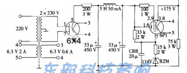
The Chinese 6X4 supply board use 5H but 230VAC per plate will provide about 200VDC 35mA with load of 2 tube of 3A5 preamp get B+ of 175VDC (200VDC-25VDC) assume that pre amp use total 20mA of 2 tubes. so V dif = 25 I = 20mA so R is 1250R
use 1250R as calculation, if I use the same 6X4 with 5H choke if input 200VAC per plate can provide about 160VDC 28mA which is enough for 3A5 2 tubes 20mA. with the same milliamp I should get near 135VDC B+
use 1250R as calculation, if I use the same 6X4 with 5H choke if input 200VAC per plate can provide about 160VDC 28mA which is enough for 3A5 2 tubes 20mA. with the same milliamp I should get near 135VDC B+
Attachments
1. There is B+ but after it there are Left B+ and Right B+. Oh Why there are 3 B+???
....Please don't think like this, a certain filter cap connected with a load is the B+ for
that load.
2. In low voltage section, there are +filament and -filament. My 4P1L used 2.1VAC filament even if I use 2.1VDC filament, there is only +2.1VDC and Ground. Why there are + and - filament?
....For a single rail supply the ground is sometimes indicted as ' - '. Here ground and -
are same.
3. the below 300K resistor of left and right B+ the link to -filament. If it is B+ it should be very high voltage, How can he link to - filament which should be very low voltage?
....question is why you don't understand Aikido is a stacked circuit and as such the
heaters need about 70 volt as reference voltage to maintain max heater cathode
voltage difference. Please don't think about this now, in due course you will
understand.
Post #76 and 77
....I don't care about this kind (cheap to build) of power supply. I like LC filtered passive
supply with high quality PT.
Please go slow and read DHTRob - Tips & Tricks. Try to avoid many junks available in the internet. You shouldn't judge a circuit without knowing its context.
Thank you very much Mr. Minhaj,
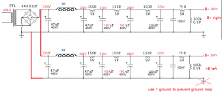
1. for B+ left and right can you draw picture after B+ and split to LEFT B+ and Right B+
2. for + and - Filament. Now I understand it. - is also ground
3. for that Akido, too difficult for me to understand if diagram not indicate voltage in every connecting points such as below 300K resistor.
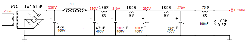
Post 76 and 77 refer to your recommendation of CLC B+, I think I found and example of it and need to modified from it to get around 135VDC 20mA. This is not use any diode tube. May be Power supply of 120VAC will provide closed to get B+ of 135VDC
However, there is no split of Right and Left B+ can you modified this picture to get left and right B+. I don't understand how to split B+.
1. for B+ left and right can you draw picture after B+ and split to LEFT B+ and Right B+
2. for + and - Filament. Now I understand it. - is also ground
3. for that Akido, too difficult for me to understand if diagram not indicate voltage in every connecting points such as below 300K resistor.
Post 76 and 77 refer to your recommendation of CLC B+, I think I found and example of it and need to modified from it to get around 135VDC 20mA. This is not use any diode tube. May be Power supply of 120VAC will provide closed to get B+ of 135VDC
However, there is no split of Right and Left B+ can you modified this picture to get left and right B+. I don't understand how to split B+.
Attachments
- Home
- Amplifiers
- Tubes / Valves
- 3A5 SE HP amp