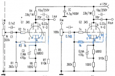
The problem with the 15K resistor is that it's always 15K, regardless of frequency. The 150H choke is about 19K at 20Hz, then that falls off. We can size the parallel feed capacitor to present more impedance as well as that happens to keep the tube lightly loaded. Above 20Hz, the impedance of the 150H choke goes up dramatically, and the impedance of the primary of the output transformer looks more like a constant reflection of whatever is loading it (provided the load isn't too far off the specifications of the secondary).
With the 15K resistor, the load on the tube is always less than 15K. If you wanted to use a plate load resistor, I would suggest a 47K plate load. This will bring your B+ up around 500V I believe. The Hammond 156C is about $15 USD, why not use a pair?
With the 15K resistor, the load on the tube is always less than 15K. If you wanted to use a plate load resistor, I would suggest a 47K plate load. This will bring your B+ up around 500V I believe. The Hammond 156C is about $15 USD, why not use a pair?
High value of plate load resistor 47K make B+ too high for me to do. I saw schematic of Chinese 3A5 Preamp in Aliexpress use 33K plate load resistor with B+ 175V to get 70VDC on 3A5 anode.
If resistance on anode can be varied depend on frequency of input, Choke 150H is easier.
Local shop has 140H 8mA 4360R which should be enough for 130VDC 8mA instead of 100VDC 10mA. B+ will be 165VDC.
Thank you very much Mr. Audiowise.
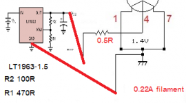
Dear Mr. Minhaj if provide Parallel 1.4V to 3A5 instead of 2.8V how the schematic of Filament part would be. Because I also use 2.1VAC pin 1+7 of my 4P1L PP instead of 4.2VAC.
Just curious of 1.4V filament to be design. Thank you in advance Mr. Minhaj
If resistance on anode can be varied depend on frequency of input, Choke 150H is easier.
3a5 parallel ra is about 4.5k ohms x 3 =13.5k ohms round to 15k ohms
3a5 parallel ra is about 4.5k ohms x 20 henry =90 henry round to 100 henry
A plate choke acts like a reactor, plate resistor does not. Two ate different.
Thank you Mr. Supernut I don't understand many things better after 30
Local shop has 140H 8mA 4360R which should be enough for 130VDC 8mA instead of 100VDC 10mA. B+ will be 165VDC.
Thank you very much Mr. Audiowise.
Dear Mr. Minhaj if provide Parallel 1.4V to 3A5 instead of 2.8V how the schematic of Filament part would be. Because I also use 2.1VAC pin 1+7 of my 4P1L PP instead of 4.2VAC.
Just curious of 1.4V filament to be design. Thank you in advance Mr. Minhaj
Attachments
Mr. Minhaj if 3A5 parafeed 0.5watts not enough to drive 50R HP, it better drive 4p1l for more power of1.5 watts. Is it good alternative?
You can do a lot better than random junk on AliExpress.Chinese 3A5 Preamp in Aliexpress use 33K plate load resistor with B+ 175V to get 70VDC on 3A5 anode.
Understood, Mr. Audiowize
Mr. Minhaj can I see your 1.4vdc parallel filament design of HP AMP? If it is not bothering you.
Mr. Minhaj can I see your 1.4vdc parallel filament design of HP AMP? If it is not bothering you.
For Mr. Minhaj's concern of 0.5watts cannot drive 50R HP. Question is how much watts of 1 5814a can make? I ever used it to drive 50R HP before I built 6080. 5814A 1 tube can drive my HP
supernut,
Post #42 -schematic is for line stage, it can be ref for HP amplifier. Even for line stage you can do much better otherwise, as audiowise mentions.
Post #43 -.5watt is not output power it is total dissipation at idle, I don't know exactly but it should be at least 3/4 times less than that.
Post #46 -my filament supply is parellel, two stages, 1st stage is well filtered regulated voltage source followed by 2nd stage high impedance constant current source.
post #47 -5814 alone can drive 50 ohms HP is loaded with a proper line out transformer or in parafeed transformer arrangement.
post #48 -wrong schematic please don't try it, you can not bias the DHT this way.
Please read:
Post #42 -schematic is for line stage, it can't be ref for HP amplifier. Even for line stage you can do much better otherwise, as audiowise mentions.
Post #42 -schematic is for line stage, it can't be ref for HP amplifier. Even for line stage you can do much better otherwise, as audiowise mentions.
Dear mr. Minhaj so #48 is wrong due to no 680R resistor to ground, am I right?
So if i add 680R resistor to pin 8 and provide 1.4Vdc to pin 1 tied with 7 and ground of DC after 680R. Then tube will work, right?
So if i add 680R resistor to pin 8 and provide 1.4Vdc to pin 1 tied with 7 and ground of DC after 680R. Then tube will work, right?
Sorry pin 4 to 680R not pin 8. I only familiar with 4p1l so forgot that ground of 3A5 is pin 4. 4p1l gnd is pin 8
I guess 680R is important. I ever saw in web 4p1l PSE also use 17R resistor to ground resistor need more watt 50 watts. Due to large current flow through it. Not sure it is called filament bias? I guess the voltage before that resistor need to be deducted from anode voltage. From mr. Audiowize i think it should be same 135v anode - 5vdc above 625R we get 130vdc which same value in datasheet. I learn a little by little. So fun to learn from people.
Mr. Minhaj, 1.4Vdc positive is to pin 1+7 (tied together) and ground of 1.4vdc is the ground after 625R
I think this is correct 2 connecting points of parallel filament, am I correct?
How to calculate 5VDC above 625R resistor.
I think this 5V from 625R has benefits
I think this is correct 2 connecting points of parallel filament, am I correct?
How to calculate 5VDC above 625R resistor.
I think this 5V from 625R has benefits
The 5V above the 625R resistor to Ground means 8mA flow equals to 0.04 watts.
How can we know that the voltage need to be 5VDC? if set to 10mA as Mr. Minhaj instead of 8mA and keep 5VDC the same resistor need to be changed to 500R
Mr. Minhaj, why need to be 5V above resistor?
How can we know that the voltage need to be 5VDC? if set to 10mA as Mr. Minhaj instead of 8mA and keep 5VDC the same resistor need to be changed to 500R
Mr. Minhaj, why need to be 5V above resistor?
but the value of resistor in another web is use by formula of R_{FIL}=\frac{V_{GK}}{I_{F}+I_{K}}
which is not equal to 625R but 10.95R
see link at Bartola UK
Filament Bias: a practical example with 3A5 DHT – Bartola(R) Valves
which is not equal to 625R but 10.95R
see link at Bartola UK
Filament Bias: a practical example with 3A5 DHT – Bartola(R) Valves
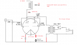
sorry again not correct. You need to connect pin1 and pin7 with a piece of wire and apply voltage across pin4 and shorted pin 1 and pin7. If we assume DC resistance of plate choke is 4000 ohms and b+ is 135 volt then passing 10ma current plate voltage will be 95 volt (4000x.01-135). 1.5uf cap need to be 4.7uf. 10K:50r will be better than 15K:50R. Why don't you go for a good output transformer such as 10K:50r gaped for 10ma dc current and be happy been simpler!
By the way yes this filament bias I was talking earlier, best sounding biasing method for my ears.
Regards
By the way yes this filament bias I was talking earlier, best sounding biasing method for my ears.
Regards
supernut, if you really build it be prepared for sweet sound +big hum + micro phony. Am saying this not to discourage you rather throwing you the challenge.
Regards
Regards
- Home
- Amplifiers
- Tubes / Valves
- 3A5 SE HP amp