Their total volumes must be the same to get the same frequency response <100hz.
but, stretch that same 80liters out in other shapes(plain qw pipe) , but retain the same tuning and its incredibly overdamped by comparison
These ‘tapped Horns’ are full of lots of 1/4 wave resonances based on length. The issue with the expanding path shape is that theyre so ‘loud’ and tightly packed as a result of the ‘horn shape’?Hey but doesn't suppose that long ports make looses ?
also, parallel walls make resonances ?
that's why TH have angled walls ?
I prefer the shapes that @BP1Fanatic does as well (straight or tapered so that junk is higher freq or filtered out by the taper shape ??)
but you DJs and sound professionals have fancy dsp/parametric eq/filters to deal with that mostly, so my ideas arent very relevant.
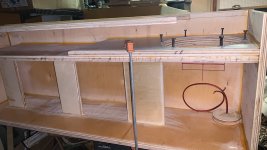
Attachments

Last edited:

Also, would you build that enclosure with that thickness of wood (1cm port length).
0.75in = 1.905cm.
0.75in = 1.905cm.
It’s kinda ‘small‘ @ 400 cm2 it gets noisy easily when driven hard and abusive like car audio peeps tend to do?Still a BR enclosure though.
That graph looks good for car audio!
Gezz, what i saw is that the PAL12 graph is around 2-3db more efficient than the OD designs (with the same 12W1600) , OD is much nice graph in the above >100Hz region
so i guess they fill have a distinct "flavour" of bass , certainly just for fun i will make one OD sometime
but guys,
1.- my budget is not huge so those 2-3db with the PAL12 will add when making more cabinets
2.- i have the amps already and they are not 18DS115 capable
3.- i am not doing car audio, but PA
i guess the PAL12 cabinet with the 12W1600 will make a good start for a limited budget sub system
so, does the 12W1600 sim graph looks acceptable ?
These ‘tapped Horns’ are full of lots of 1/4 wave resonances based on length. The issue with the expanding path shape is that theyre so ‘loud’ and tightly packed as a result of the ‘horn shape’?
I prefer the shapes that @BP1Fanatic does as well (straight or tapered so that junk is higher freq or filtered out busy the taper shape ??
Hence,
Straight flare TH = tapped QUARTER WAVE pipe or tube (TQWP or TQWT).
Negative flare TH = tapped & tapered QUARTER WAVE tube or pipe (T-TQWT or T-TQWP).
I think double fold and higher does some extra filtering.
Single fold is the easiest build and provides the smallest footprint if you don't mind have columns in your room.
(The 400 cm2 and 1.0cm in Ap/Lpt are merely there to make Vrc/Lrc available as a vented box to stretch out (LRC) 225cm to a certain tuning while retaining the same 80 liter box volume )Also, would you build that enclosure with that thickness of wood (1cm port length).
0.75in = 1.905cm.
it’s all 400cm2…
this is particularly useful when trying to seperate TL from BR boxes and grow an appreciation/understanding for how they are very much different at the ends of the alignments instead of thinking they’re all the same I guess?
Last edited:
You model TL enclosures with the same functions as you do BR enclosures in HR.
If you want to use a positive or negative flare, then use the segments. However, you can use the same segments to model a BR enclosure, just keep the flare straight.
If it looks and quacks like a duck, then it's a duck.
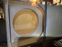
The Coupling Chamber TL pic is all you need see to know it's nothing more than a fancy BR enclosure.
If you want to use a positive or negative flare, then use the segments. However, you can use the same segments to model a BR enclosure, just keep the flare straight.
If it looks and quacks like a duck, then it's a duck.
The Coupling Chamber TL pic is all you need see to know it's nothing more than a fancy BR enclosure.
I dont think you understand there’s a difference or are interested in what/why.
staring at freq response simulation screens instead of electricAl impedance/phase or the details of the vent output(resonance and cancelations do to 1/4 wavelengths, etc) has made you a duck, ‘quack, quack’ 😝
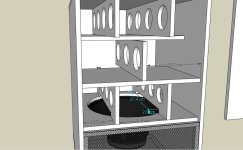
After all, this is a just a BR (transflex) if you look closer (if using your duck method of identifying ) where would find much of the extra wood isnt creating anything different?
staring at freq response simulation screens instead of electricAl impedance/phase or the details of the vent output(resonance and cancelations do to 1/4 wavelengths, etc) has made you a duck, ‘quack, quack’ 😝
After all, this is a just a BR (transflex) if you look closer (if using your duck method of identifying ) where would find much of the extra wood isnt creating anything different?
Attachments
Last edited:
No it doesn't. You remove those 2 panels and it's STILL a BP6S enclosure. And, it could still be a negative flare TH with a compression (coupling) chamber. Remember Tom Danley's patent pictures?
All TH's (positive, straight, & negative flare) = BP6S.
All single chamber enclosures with a positive, straight, negative flare port = BR.
Did you read Martin J. King's paper about BLH/RLH turning into TL???
BLH/RLH = BR with positive flare port.
TL = normally a BR with a negative flare port, but do have positive and straight flare ports.
BR = BR with a straight flare port.
You can VISUALLY look at the internals of an enclosure to see what type enclosure it is WITHOUT ANY impedance measurements. The Coupling Chamber TL version proves my point.
Like I said before, what happens >100hz don't matter because we are in a SUBwoofer forum. 99% of the time, SUBwoofers are crossed over <100hz.
In my car, I run the head unit at <120hz and the SUBwoofer amplifier at <200hz or whatever the highest setting is for the combined steep slope. There's your 1%.
In my home, all AVR's run <80hz and depending on the SUBwoofer amplifier (I'm using another AVR, 2 channel receiver, & dedicated amplifier), I use the highest low pass filter setting for the combined steep slope. I have four 5.1 systems, a 3.1 converted sound bar system, and two 2.1 systems under the roof. I like my audio in whatever room I'm in, including 2 of the 5.1 systems in the basement and one of the 2.1 systems in the garage (I work on cars as a side hustle).
Last edited:
I wish there was a way to illustrate this without it just looking like a bunch of HF sine wave shapes?
I’m far more Intersted in how these things function and are somewhat different than finding people to agree with what they should be named ?
if you can’t even identify the first qw mode in your own tapped tapered pipes then how would you even know what it’s doing besides just wanting to argue?
I’m far more Intersted in how these things function and are somewhat different than finding people to agree with what they should be named ?
if you can’t even identify the first qw mode in your own tapped tapered pipes then how would you even know what it’s doing besides just wanting to argue?
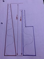
Attachments
Last edited:
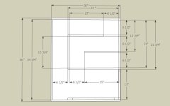
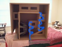
Stepped T-TQWT, which is also a BP6S.What is this? bp6s, stepped Ttqwtube or just a long skinny bass reflex?
It would be a BR enclosure if the driver was mounted on an outside panel.
Bandpass enclosure = internal driver mounting.
I wish there was a way to illustrate this without it just looking like a bunch of HF sine wave shapes?
I’m far more Intersted in how these things function and are somewhat different than finding people to agree with what they should be named ?
if you can’t even identify the first qw mode in your own tapped tapered pipes then how would you even know what it’s doing besides just wanting to argue?
Positive flare = big and loud.
Negative flare = small and low.
Straight flare = easy build, no angles.
Hofmann's Iron Law...loud, low, small...pick 2.
easy build.... no angles and a good compromise between loud low and small
https://soundagency.fr/docs/sath112-lex-un-tapped-horn-12-puissant/
https://soundagency.fr/docs/sath115-rm-compact-et-super-performant/
https://soundagency.fr/docs/sath112-lex-un-tapped-horn-12-puissant/
https://soundagency.fr/docs/sath115-rm-compact-et-super-performant/
If you do Stepped flares, then the same laws apply. Still no angles tho!
I think constant straight flare, it can go either way depending on the cross section area.
Compare a
6" high throat and 12" high mouth
to a
9" high throat and 9" high mouth
to a
12" high throat and 6" high mouth
and all 3 models must have the same width and 10ft total length.
You will see that you can shorten the 12>6 model to have the same f3 as the 6>12 model and you will need to lengthen the 6>12 model to have the same f3 as the 12>6 model...Hofmann's Iron Law.
We will also know how close the 9" model is to the other 2 models.
Last edited:
- Home
- Loudspeakers
- Subwoofers
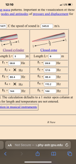
- $325 Lab 12 based PA tapped horn ~ 35Hz extension