Due to my past experience of 4p1l push pull amp. I do without LTSPICE. It is not good. High voltage just simple CLC and volt is too high 298vdc b+ instead of 250VDC B+ i use resistor to drop volt and it affects sound quality. I have to ensure before build 6SN7 45 SE 2 watts. My 4p1l PP is my horror dream. If i am hurry build without LTSPICE, it will definitely have problem that Basic diyer as me can't solveWell you can just build it, no need to get hung up on LTspice ;-)
It's a proven design.
Jan
You have connected the main diode bridge in reverse, and anyway, your bizarre regulator probably consumes too much current.Mr.Elvee's neg schematic get -77VDC but when input to regulated it failed.
Here is yet another example of proven and tested regulator, but it is overkill (it is the auxiliary regulator in the secondary schematic):
https://www.diyaudio.com/community/...for-testing-tube-projects.327831/post-5555313
A much simpler circuit would be usable for such an application, if you use it in combination with the capacitive supply:
The MOS is the first I found, but it is vastly overdimensionned
Dear Mr. V4LVE,I couldnt sleep very well, so i breadboarded a regulator for the HV for you. My main problem with your regulator was two things:
A mosfet leaks slightly from gate to source, say .5mA to account for this you need a relatively low value of resistance from B+ to gate, by using a 2mA current source this is taken care of and the current source will work down to about 5V
secondly one wants to keep the dissipation out of the driver transistor this is better for voltage stability, i did this by building a cascode out of a high gain BC547 and a MJE340.
Attached the schematic, and a picture of the breadboarded regulator, with resistor instead of current source(I ran out of MJE350)
Cheers,
V4LVE
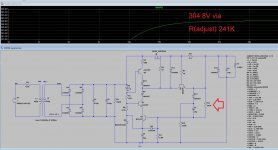
Thank you very much again. I have tested in LTspice. However if I want 305V 86mA I random test till I found the value of R adjust (R11) as 241K.
How to use mA and voltage to calculate the value of R adjust.
Thank you.
Attachments
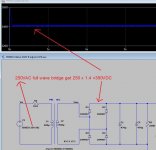
I just know that 1 VAC full wave bridge will be 1.4 times. so I use L1 =400U and L2 = 760u to get about 1.4 time of VDC. if input 250VAC then I get 350VDC.You have connected the main diode bridge in reverse, and anyway, your bizarre regulator probably consumes too much current.
Here is yet another example of proven and tested regulator, but it is overkill (it is the auxiliary regulator in the secondary schematic):
https://www.diyaudio.com/community/...for-testing-tube-projects.327831/post-5555313
A much simpler circuit would be usable for such an application, if you use it in combination with the capacitive supply:
View attachment 1083173
The MOS is the first I found, but it is vastly overdimensionned
I have input your schematic and get 305VDC from 250VAC however it can not adjust output voltage via 470K trimpot. as per attachement.
My 50 aging eyes are sore from LTspice. Tomorrow might be better to study.
Thank you very very much
Attachments
In LTspice, the AC voltage is the peak value (250V), and when you rectify it you don't need the 1.4 factor. You get a multiplication due to the inductances ratio of the transformer (they are insanely low BTW, fortunately it is a sim, in the real world there would be sparks and smoke).
The regulator circuit I provided must be used with the capacitive supply shown previously, and not be directly connected to the transformer.
You should probably try simple, low voltage circuits first. Your current level of expertise is insufficient to work with potentially lethal circuits
The regulator circuit I provided must be used with the capacitive supply shown previously, and not be directly connected to the transformer.
You should probably try simple, low voltage circuits first. Your current level of expertise is insufficient to work with potentially lethal circuits
Dear Mr. V4LVE,
Thank you very much again. I have tested in LTspice. However if I want 305V 86mA I random test till I found the value of R adjust (R11) as 241K.
How to use mA and voltage to calculate the value of R adjust.
Thank you.
You take a ballpark figure, and add a 50K pot and turn until you reach 305V.
In theory its about 6.2+0.65V over 5K6 (which should have been 6K8 instead) from this you can deduce the current as 1mA approximately.

Can you have any simple simulation of AC to DC of full wave without L1 L2In LTspice, the AC voltage is the peak value (250V), and when you rectify it you don't need the 1.4 factor. You get a multiplication due to the inductances ratio of the transformer (they are insanely low BTW, fortunately it is a sim, in the real world there would be sparks and smoke).
The regulator circuit I provided must be used with the capacitive supply shown previously, and not be directly connected to the transformer.
You should probably try simple, low voltage circuits first. Your current level of expertise is insufficient to work with potentially lethal circuits
for example AC250 to DC 350
I want to simulate as real world but in the real world there is no 1.4x inductor.
i think LT spice can convert 250VAC to 350VDC, but i don't know how from my little knowledge.
You take a ballpark figure, and add a 50K pot and turn until you reach 305V.
In theory its about 6.2+0.65V over 5K6 (which should have been 6K8 instead) from this you can deduce the current as 1mA approximately.
1. what is ballpark figure?
2. 50K pot is not enough due to the adjust resistor is 241k
250VAC is too low for 350VDC under load, you have to account for resistive losses under load.Can you have any simple simulation of AC to DC of full wave without L1 L2
for example AC250 to DC 350
I want to simulate as real world but in the real world there is no 1.4x inductor.
i think LT spice can convert 250VAC to 350VDC, but i don't know how from my little knowledge.
in my 4P1L PP 230VAC after diode bridge and get about 326VDC and after C L C 5H 130ohm and bleeding 220K resister the voltage is about 298VDC. with total 132.5mA load.250VAC is too low for 350VDC under load, you have to account for resistive losses under load.
326 VDC / 230 VAC = 1.4X
with 132.5mA load 298VDC / 230 VAC = 1.296X ( my 4P1L PP get a serious problem of too high voltage of 298VDC I need to drop via using 310R resistor to get around 255VDC over anode) Thai is my bad experience about too high VAC of 230VAC for just 255VDC
then I use 1.4X to multiply with 250VAC = 350VDC
with 84-86mA load of 2 6SN7 and 45 which are less load than 132.5mA of 6n2 x2 4P1L x 4 132.5mA I think the factor of 1.296X might increase to >1.35X
for 310VDC of B+ to feed with 45 to get around 305VDC over 45 anode.
Hence 250VAC x 1.35 = 337.5VDC and use HV to drop to 310VDC.
The basic rule is to use a voltage 1.414 larger than the rms value, like 325V for a 230V mains, but you need to account for the losses of the transformer, resistive and inductive, to reflect the reality.Can you have any simple simulation of AC to DC of full wave without L1 L2
for example AC250 to DC 350
I have given numerous examples on the forum, but they might become difficult to locate, due to the forum changes.
I'll search my hard disks, and give you some info later, but really, if you cannot master such simple issues, you shouldn't venture past 100V. Unlike cats, you only have one life, and with 300V, it could go very easily
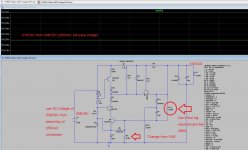
Try to simulate with 338VDC (omit my incorrect AC / DC conversion). However, the value of resistor to adjust the voltage still very high at 298K.
I think I can't find trim pot of this high value. Most trim pot sell nearby is about 100K only.
I think I can't find trim pot of this high value. Most trim pot sell nearby is about 100K only.
Attachments
The comment #50 is based on real experience of my 4P1L PP. I measure voltage as I have mentioned.The basic rule is to use a voltage 1.414 larger than the rms value, like 325V for a 230V mains, but you need to account for the losses of the transformer, resistive and inductive, to reflect the reality.
I have given numerous examples on the forum, but they might become difficult to locate, due to the forum changes.
I'll search my hard disks, and give you some info later, but really, if you cannot master such simple issues, you shouldn't venture past 100V. Unlike cats, you only have one life, and with 300V, it could go very easily
Targeting 255VDC for 4P1L anodes. the seller told me to use 230VAC-0 transformer.
However, I failed because of B+ voltage even load of 132.5mA still too high of 298VDC (target only 255VDC) I need to drop via 1 resistor to get 255VDC.
That make sound of my 6N2 4P1L PP not good.
Seller still insist that 230VAC - 0 transformer is correct for 255VDC but why I got 298VDC ? with load 132.5mA
That experience made me use only 250VAC for 310VDC of my new project 45SE (CLCLRC 338VDC ---> HV reg ----> 310VDC B+ ---> OPT---> 305VDC on anode)
My 4 X 6SN7 preamp target with 265VDC on anode I use 300VAC-0-300VAC with 5U4G tube rectify the voltage is also too high (not recognise but around 340VDC). I need resistor to drop voltage to 265 for my 6SN7. That make sound not good again.
My trouble is too high VDC every projects I did in the past.
I don't want to make same mistake as 45SE
due to expensive 45 tube. I plan to build cheap preamp like 4P1L x 2 to replace my old 6SN7 x4 ( this is the way to test both HV reg 250VDC ( 180VDC via gyrator) + bias -10.2VDC and filament Reg 2.1VDC) if 3 regulators works, I will use with 45
due to cheap 4P1L if everything fail, I will not sad much 4P1L is cheaper than 45
Last edited:
The basic rule is to use a voltage 1.414 larger than the rms value, like 325V for a 230V mainsThe basic rule is to use a voltage 1.414 larger than the rms value, like 325V for a 230V mains, but you need to account for the losses of the transformer, resistive and inductive, to reflect the reality.
I have given numerous examples on the forum, but they might become difficult to locate, due to the forum changes.
I'll search my hard disks, and give you some info later, but really, if you cannot master such simple issues, you shouldn't venture past 100V. Unlike cats, you only have one life, and with 300V, it could go very easily
- it is very YESSSS.
I got this value (326VDC) after bridge diode and after CLC I got 298VDC. Now you understand my concern of too high voltage beyond the anode need (250-255VDC)
The transformer seller might recommend more than 250VAC - 0 for 310VDC need again. I have not ask him but I think as always He will recommend me 270VAC-0 or even 290VAC-0 to my 45 SE.
Last edited:
You can take a fixed metal film resistor of 270K 1W plus a 50K 0.25-0.5W pot in series. I don't think you need adjustment over the entire range.Try to simulate with 338VDC (omit my incorrect AC / DC conversion). However, the value of resistor to adjust the voltage still very high at 298K.
I think I can't find trim pot of this high value. Most trim pot sell nearby is about 100K only.
Also for linear power supplies, it is customary to have the AC voltage roughly equal to the DC voltage. This is to account the headroom the regulator needs to work properly. And also because the input voltage of the transformer(mains) can vary +-15%. Meaning your supply WILL drop out if your mains voltage ever goes below -10%
I recommend a transformer of 280-290VAC for 305VDC output.
Slightly offtopic.
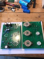
I still have boards for my tube regulated supply using 3x EL34 available if you want, its very nice but needs 450V input to produce 305V 300mA output. Pic attached.
Attachments
Thank you very much.You can take a fixed metal film resistor of 270K 1W plus a 50K 0.25-0.5W pot in series. I don't think you need adjustment over the entire range.
Also for linear power supplies, it is customary to have the AC voltage roughly equal to the DC voltage. This is to account the headroom the regulator needs to work properly. And also because the input voltage of the transformer(mains) can vary +-15%. Meaning your supply WILL drop out if your mains voltage ever goes below -10%
I recommend a transformer of 280-290VAC for 305VDC output.
Slightly offtopic.
I still have boards for my tube regulated supply using 3x EL34 available if you want, its very nice but needs 450V input to produce 305V 300mA output. Pic attached.
Then I have question (off topic) how I handle my 298VDC (over voltage) of my old amp 4P1L PP to get 255VDC without using 300R resistor.
When I told transformer seller I need 255VDC, He recommend me 230VAC - 0 as you and mr. Elvee recommend.
However when I built, I got very serious problem of over voltage of 298VDC from 230VAC-0 transformer.
suppose I buy 290VAC - 0 transformer for my 310VDC 45SE project
without HV reg, using only CLC. I am certain voltage will be about 290 x 1.35 = 391.5 after CLC which 81VDC more than I need.
Last edited:
The transformer shop also recommend me to buy 45 SE from local tube amp shop nearby instead of building myself. However it costs THB 36000 for this mono block amp. I can't afford.
Even use my tubes, he discount me only THB 6,000 to THB 30,000. I still can't afford.
However the sound of this little 2 watts is very good. 45SE is a lot better than my 4P1L PP amp Ultra Linear 6-8 watts.
Even use my tubes, he discount me only THB 6,000 to THB 30,000. I still can't afford.
However the sound of this little 2 watts is very good. 45SE is a lot better than my 4P1L PP amp Ultra Linear 6-8 watts.
Attachments

I have found some reference data.
First, this one:

Lm is the magnetizing inductance; to find the magnetizing inductance for a typical transformer, divide 3000 by the number of VA: for example, a 100VA would have 30H.
Rtot and Ltot are the series parasitic components; to find the value, divide the relevant figure by the VA, for example for 100VA, the total series resistance would be 47 ohm. This includes the primary and transformed secondary resistance. For a 1:1 230V to 230V transformer, the primary and secondary would each have 23.5 ohm DC.
The values are typical for each type of construction and can vary widely from one manufacturer to the other.
This one is similar, but includes the saturation effects. However, it has been a long time, and I don't remember how to use it.....

First, this one:
Lm is the magnetizing inductance; to find the magnetizing inductance for a typical transformer, divide 3000 by the number of VA: for example, a 100VA would have 30H.
Rtot and Ltot are the series parasitic components; to find the value, divide the relevant figure by the VA, for example for 100VA, the total series resistance would be 47 ohm. This includes the primary and transformed secondary resistance. For a 1:1 230V to 230V transformer, the primary and secondary would each have 23.5 ohm DC.
The values are typical for each type of construction and can vary widely from one manufacturer to the other.
This one is similar, but includes the saturation effects. However, it has been a long time, and I don't remember how to use it.....
Let's take an example: a 60VA, 230V to 250V EI transformer having a modern, split-bobbin construction (side-by-side).
First, the magnetizing inductance: Lm=3000/60= 50H
The secondary inductance is (250/230)²*50=59.1H
The total leakage inductance is 6118/60=102mH
The total series resistance is 4700/60=78.3 ohm
This is the simulated result:

First, the magnetizing inductance: Lm=3000/60= 50H
The secondary inductance is (250/230)²*50=59.1H
The total leakage inductance is 6118/60=102mH
The total series resistance is 4700/60=78.3 ohm
This is the simulated result:
Attachments
- Home
- Amplifiers
- Power Supplies
- 305Vdc HV regulator adjustable via zener diode too slow 7seconds