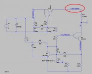
Total zener 100V + 100V + 60V = 260VDC output get 250 using 2SK3564.Something like this:
View attachment 1083497
The MOS has to be an old generation type, with a good SOA, like IRFP450
1. Do we need Heatsink for 2SK3564 or just put it on "Aluminum Chassis" of the amp directly.
2. In simulation I use load of 0.1325A of total current of my 4P1L x 4 and 6N2 x 2, is it correct?
Attachments
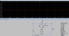
Yes, it will dissipate ~50V*0.133= 6~7W, but you should take a sufficient margin. The chassis could work, if it is thick enough (>=1.5mm) and if it not already hot due to other devices. A good electrical insulation is requiredTotal zener 100V + 100V + 60V = 260VDC output get 250 using 2SK3564.
1. Do we need Heatsink for 2SK3564 or just put it on "Aluminum Chassis" of the amp directly.
I don't know, you should ask in the Tubes section2. In simulation I use load of 0.1325A of total current of my 4P1L x 4 and 6N2 x 2, is it correct?

Oh Thank you I just know Ctrl + Alt.You have the LTspice setup. Just put the mouse pointer on the FET and press Ctrl and Alt simultaneously, the mouse pointer changes to a thermometer, click and the curve will show the dissipation.
Jan
Ahhh. It just Alt. and it shows dissipation watts of MOSFET about 6.47Watts How to know it is hot and require heatsink or not?
Normally you check the data sheet for the thermal resistance between junction and case, which gives you the temp difference between junction and case with that dissipation. If it is too high you figure in a heatsink. I would do it but right now am busy, maybe someone else will chime in.
Or follow the upcoming advice from other members to just put it on a heatsink and hope for the best ;-)
Jan
Or follow the upcoming advice from other members to just put it on a heatsink and hope for the best ;-)
Jan
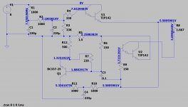
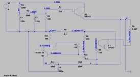
Does voltage Sine (0 325 50) equal to Transformer of 280VAC -0 ? Thank you. The negative need to be adjust between -56VDC to - 70VDCThis is the circuit including the negative auxiliary supply with a 250K load:
View attachment 1083276
Actually it needs around -62VDC but for safety start at -70VDC will be better.
However, I think split small winding with main transformer can be done about 50mA 60VAC.
Main transformer will have 280VAC - 0 100mA and 60VAC - 0 50mA
For filament section of 45 and 6SN7 ( I have not think about it yet but if using filament regulator like ROD Coleman or Regulator of Mr. Enzo6C33)
https://nekolab.it/2021/04/18/billie-dht-tube-line-preamplifier/
However, it is off topic of HVreg. I will post later if I have more information. but for 2.5VDC I think I need around 8VAC - 0 Transformer to get about 8VDC for filament (get 5.59VDC - 3.09VDC = 2.5VDC approx). However with no ground on filament. I am not sure 45 tube without ground will damage tube??
I have not study it yet.
Attachments
Last edited:
I don't know the purpose of U2 (actually I don't know all of components). I gather information from the website, then try to simulateWhts the purpose of U2??
It's C is grounded ...
Jan
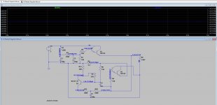
https://nekolab.it/2021/04/18/billie-dht-tube-line-preamplifier/
For example, this website do 4P1L filament bias of 8.75V (2.1VDC on filament) then I simulate him.
Then I think I can apply to 45 (as 2nd picture attachment)
Attachments

Then I try omit lower section (no U2 and no small transistor). Same result of 2.5VDC 1.5A. but with more benefit of smaller PCB too.Whts the purpose of U2??
It's C is grounded ...
Jan
I think the low section is to fine tune the "current" to be exactly 1.5A for 45 and if decrease source voltage to 4.75VDC can apply to 4P1L 550mA 2.1VDC.
Attachments
Last edited:
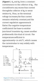
Too difficult for meIf you want constant current, design a current source. Right now you design a voltage source and try to make it behave like a current source. Impossible task.
Decide what you want, and design that.
Jan
Need to study more
https://www.electronics-notes.com/a...transistor/active-constant-current-source.php
https://www.edn.com/circuit-achieves-constant-currentover-wide-range-of-terminal-voltages/
I am not engineer, may be I go to ask some engineer in university if i have time
Attachments
Last edited:
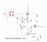
should be like this. But it fail
https://audiophilediyer.com/dht-filament-regulator/
However Mr. Enzo schematic is success.
It seem resemble.
https://audiophilediyer.com/dht-filament-regulator/
However Mr. Enzo schematic is success.
It seem resemble.
Attachments
Last edited:
My mistakes of previous schematic (a lot of mistake from Mr. Enzo schematic due to opposite side make me confuse) Forgive my IQ.Whts the purpose of U2??
It's C is grounded ...
Jan
I think now correct.
Thank you very much for notify me.
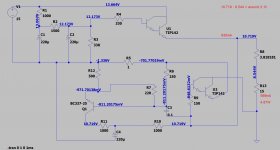
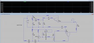
New problem there is no 0.2R of R5 in real world then it is fail in the real world
Then increase voltage to 6.5VDC and change R5 to 0.5R (1 R parallel)
Attachments
Last edited:
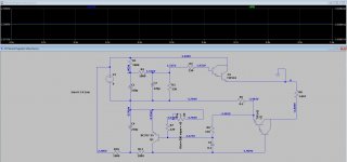
U1 drives its current into ground. That seems useless.
I said before: do you want a voltage regulator or a current regulator? You are on an impossible path right now trying to do two things that cannot be done together.
Think about it. If you want to stabilise the current, that will result in some voltage as a result. Then if you want to manipulate that voltage, you change the curent. You have the wrong idea.
Verify that your circuit works as you want. If R8 is your load, check the regulation by changing it's value. If you want constant current, does it stay constant when you change R8? If you want constant voltage, does it stay constant when you change R8?
Can you tell us what it is you want to do?
Jan
I think voltage is 1st priority to get 2.5VDC let current consume by tube 1.5AU1 drives its current into ground. That seems useless.
I said before: do you want a voltage regulator or a current regulator? You are on an impossible path right now trying to do two things that cannot be done together.
Think about it. If you want to stabilise the current, that will result in some voltage as a result. Then if you want to manipulate that voltage, you change the curent. You have the wrong idea.
Verify that your circuit works as you want. If R8 is your load, check the regulation by changing it's value. If you want constant current, does it stay constant when you change R8? If you want constant voltage, does it stay constant when you change R8?
Can you tell us what it is you want to do?
Jan
May be LT1963 is better option
Attachments
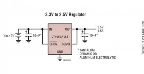
Don't give it up yet! You have made an important decision: you want a voltage regulator!
Look at some voltage regulators on the net. The LT1963 is an option, but a discrete one like the circuits you've been playing with are also good. Also look at 'capacitance multiplier'. It's not a regulator in the strict sense, but since the load is constant it doesn't matter too much. Depends how much effort you want to put in and how much you want to learn 😎
Jan
thank you so much Jan. I try to understand your technical message above. That is beyond my knowldege now.
Capacitance multipier, what is it?
R8 is load, then I control both Volt and amp by lock source to be 6.5Vdc fix R5 to be 0.5R then add 0.5K trimpot to replace R4 then I have 2 of 0.5K trimpot to little fine tube control of voltage and current
Capacitance multipier, what is it?
R8 is load, then I control both Volt and amp by lock source to be 6.5Vdc fix R5 to be 0.5R then add 0.5K trimpot to replace R4 then I have 2 of 0.5K trimpot to little fine tube control of voltage and current
Last edited:
- Home
- Amplifiers
- Power Supplies
- 305Vdc HV regulator adjustable via zener diode too slow 7seconds