I would not use fixed bias on a SE amp, especially on $125 tubes.separate fixed bias
Self-bias is MUCH safer, simpler, self-adjusting. And the datasheet tells you that:

Sorry, I made some confusions in post #60: some values are expressed in units (example, ohm*VA) meaning that in order to arrive at the resistance, you need to divide the parameter by the VA figure for the resistance value.
Others show the formula required to arrive at the correct result (ohm/VA). I know what I mean, but these inconsistencies are certainly puzzling for other people. Anyway, I have worked out an example showing how these values are meant to be used.
Also note that this is for 230V/50Hz only, and the values are for guidance only: depending on the construction/materials quality, your mileage may vary
Thank you very much I will study tomorrowLet's take an example: a 60VA, 230V to 250V EI transformer having a modern, split-bobbin construction (side-by-side).
First, the magnetizing inductance: Lm=3000/60= 50H
The secondary inductance is (250/230)²*50=59.1H
The total leakage inductance is 6118/60=102mH
The total series resistance is 4700/60=78.3 ohm
This is the simulated result:
View attachment 1083271
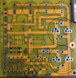
PS. This supply PCB will ensure correct wiring before input to HV REG
Attachments
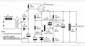
Just found simple HV reg for newbie in power supply. Might not efficient as previous circuit but easy.
i hope it can help me not destroy power supply so I share schematic and wait for comment.
no need to make PCB because it is widely sell and inexpensive about 1.5 usd
i hope it can help me not destroy power supply so I share schematic and wait for comment.
no need to make PCB because it is widely sell and inexpensive about 1.5 usd
Attachments
I would not use fixed bias on a SE amp, especially on $125 tubes.
Self-bias is MUCH safer, simpler, self-adjusting. And the datasheet tells you that:
View attachment 1083304Thank you then 4p1l preamp fixed bias is better to try until success. Tube is inexpensive if failed
230vac to 250vac transformer get only 294VDC?Let's take an example: a 60VA, 230V to 250V EI transformer having a modern, split-bobbin construction (side-by-side).
First, the magnetizing inductance: Lm=3000/60= 50H
The secondary inductance is (250/230)²*50=59.1H
The total leakage inductance is 6118/60=102mH
The total series resistance is 4700/60=78.3 ohm
This is the simulated result:
View attachment 1083271
Mine 220vac to 230vac got VDC out of 326vdc after full bridged with 132.5 mA load. And 298vdc after choke and 220K bleeding resistor
I don't know why it is not consort with your simulation
In case of tube rectify such as 5Y3, normal practice is use 20Vdc to minus from center tap tr.
for example need 350VDC B+, tr is 330 - 0 - 330
i guess 5Z3 volt drop about -50 VDC BUT 330 x 1.414 = 466VDC then -50 VDC = 416VDC still too high for 350VDC need about 66VDC
Which i don't understand
Only possible close is half wave rectify of 1.21 then 330 x 1.21 = 399VDC then -50 = 349VDC now match B+ need of 350VDC but I think it is not 1.21X factor
Last edited:
I think Mr. Jan Didden are specialized in HV reg desing for tube and in someway I think he is the make of T-Reg HV500V 200mA. if I am not wrong.It takes a long time to charge C3 through R1, the RC timeconstant is 2.4secs. Make R1 much smaller and it will be OK.
Jan
If -56 to -62v need then -70 start is safe then gradually increase to -62vdcI would not use fixed bias on a SE amp, especially on $125 tubes.
Self-bias is MUCH safer, simpler, self-adjusting. And the datasheet tells you that:
View attachment 1083304
is it correct practice for fixed bias
I have opted for a 60VA example. What is yours rating?230vac to 250vac transformer get only 294VDC?
Mine 220vac to 230vac got VDC out of 326vdc after full bridged with 132.5 mA load. And 298vdc after choke and 220K bleeding resistor
I don't know why it is not consort with your simulation
230VAC 200-250mA = 230 x 0.2 or 230 x 0.25 = 46 - 57.5VA If I am not wrong I made this amp for 5 years. I forgot the mA of transformer. But scientist can find outI have opted for a 60VA example. What is yours rating?
230VAC --> 326VDC after bridge --> after CLC --> 299VDC (all measure with load of 132.5mA)
backward engineer can find out my mA of my transformer. I am certain.
However I confirm the AC to DC ( even with load) get too high value.
All of these experience is form and made the reason why I decide only 250VAC -0 Transformer for 305-310VDC not 280 or 290-0 as almost people told me too even local transformer seller tell me.
I believe I am wrong at 250VAC to get 310VDC. Not anybody support me to use 250VAC for 310VDC 84-86mA load.
However I need a prove in number that if you need 310VDC you should get 280-290VAC TR.
All commercial Chinese amp also use simple method, if you want any DC you just -20VDC for example need 250VDC then 250-20 = 230VAC need
it also apply for center tab (tube rectify) need 250VDC need 230-0-230.
PS. My 4P1L PP is a prove in realistic number that if you want 250VDC you not need 230VAC you just need only 205VAC -0 Transformer
For newbie or commercial guy like (local Transformer seller) they are not graduate engineer. However they use -20VDC as criterion for most commercial tube amp in the market such as 6P15 EL34 KT88 EL84 which are standard commercial amp. Hence he remember -20VDC from B+ to get VAC.
But real engineer can prove it why it need AC and DC close voltage to each another ( take a true load in equation).
I am a financial guy, only number I trust.
Last edited:
You cannot tell the transformer's VA by simply measuring the current: there is the power-factor and other parameters to take into account.
If you measure the DC resistance of the primary, this will give a good idea of the actual VA figure.
Also, in my sim, I didn't take into account the regulation of the transformer: its output is 250V, but open-circuit, not under load. In fact, such a transformer would be specified as 225V nominal. A 10% regulation is normal for such a relatively small transformer
I can't measure DC resistance of primary now. I don't want to take riskYou cannot tell the transformer's VA by simply measuring the current: there is the power-factor and other parameters to take into account.
If you measure the DC resistance of the primary, this will give a good idea of the actual VA figure.
Also, in my sim, I didn't take into account the regulation of the transformer: its output is 250V, but open-circuit, not under load. In fact, such a transformer would be specified as 225V nominal. A 10% regulation is normal for such a relatively small transformer
the point is 230VAC get final B+ of 298VDC which too much for my 250VDC requirement B+ That figure tell me that for newbie as me to get 250VDC on 4P1L anode do not use 230VAC (close to 250VDC) but use transformer about 205VAC to get closer to final B+ of 250VDC on anode.
As Newbie in tube, many readers who read this will understand me and I am certain that many newbie who make tube amp will encounter same problem as mine about "over voltage even with load" when use -20VDC formula to minus to get close AC (250VDC-20 use 230VAC transformer)
in this case of 45SE I am certain. Newbie who use 290VAC - 0 Transformer for 310 VDC B+ will get "over voltage with 86mA load)
Hence if they has no HV regulator on hand, they gonna use big watt R to drop the voltage and it will seriously detriment the sound quality via that "big watt resistor".
There is no risk if you do it as it should be done. I hope you didn't intend to make the measurement with the mains connected!I can't measure DC resistance of primary now. I don't want to take risk
With the transformer unplugged, there is absolutely no risk
There are probably solutions: one would be to swap the primary and secondary, on the condition there is no other winding, like heater etc. That would be dangerous, but with just two windings, it is possible and safe.the point is 230VAC get final B+ of 298VDC which too much for my 250VDC requirement B+ That figure tell me that for newbie as me to get 250VDC on 4P1L anode do not use 230VAC (close to 250VDC) but use transformer about 205VAC to get closer to final B+ of 250VDC on anode.
As Newbie in tube, many readers who read this will understand me and I am certain that many newbie who make tube amp will encounter same problem as mine about "over voltage even with load" when use -20VDC formula to minus to get close AC (250VDC-20 use 230VAC transformer)
in this case of 45SE I am certain. Newbie who use 290VAC - 0 Transformer for 310 VDC B+ will get "over voltage with 86mA load)
Hence if they has no HV regulator on hand, they gonna use big watt R to drop the voltage and it will seriously detriment the sound quality via that "big watt resistor".
Another option is to use a L-input filter -but you would have to get hold of a suitable choke-
Yet another option is to use a rudimentary regulator to drop the excess voltage: it can be as simple as a big MOS and a string of zeners, and it would improve the supply quality
This is the "Happy solution" answer for newbie to solve the over voltage problem. Can you help drawing "a big MOS and a string of zeners". Suppose would like to drop 298VDC to 250VDC. If it is not bother you.There is no risk if you do it as it should be done. I hope you didn't intend to make the measurement with the mains connected!
With the transformer unplugged, there is absolutely no risk
There are probably solutions: one would be to swap the primary and secondary, on the condition there is no other winding, like heater etc. That would be dangerous, but with just two windings, it is possible and safe.
Another option is to use a L-input filter -but you would have to get hold of a suitable choke-
Yet another option is to use a rudimentary regulator to drop the excess voltage: it can be as simple as a big MOS and a string of zeners, and it would improve the supply quality
Where do you measure your B+? At the output of your filter, or between anode and cathode of the valve?Thank you very much.
Then I have question (off topic) how I handle my 298VDC (over voltage) of my old amp 4P1L PP to get 255VDC without using 300R resistor.
When I told transformer seller I need 255VDC, He recommend me 230VAC - 0 as you and mr. Elvee recommend.
However when I built, I got very serious problem of over voltage of 298VDC from 230VAC-0 transformer.
suppose I buy 290VAC - 0 transformer for my 310VDC 45SE project
without HV reg, using only CLC. I am certain voltage will be about 290 x 1.35 = 391.5 after CLC which 81VDC more than I need.
Thank you i will simulate mineSomething like this:
View attachment 1083497
The MOS has to be an old generation type, with a good SOA, like IRFP450
Measure B+ at output of filter get 298VDC. at the + polar of last Capacitor of CLC 230VAC ---> 4 Bridge diodes ---> 326VDC ----> CLC 298VDC.Where do you measure your B+? At the output of your filter, or between anode and cathode of the valve?
- Home
- Amplifiers
- Power Supplies
- 305Vdc HV regulator adjustable via zener diode too slow 7seconds