where you put the driver on the x5b ?
Maybe it's better to create a different thread to discus the x5b.
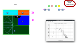
The driver is placed where the color changes, the driver placement are defined by the models available on Hornresp, in this case it was the CH3. Check attachment #1 and remember always to check System Model.
DL for doing sims
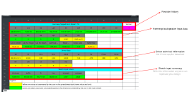
The sim output are available at the spreadsheet page inside the CAD files that you download, the user can also export the TXT file to hornresp with all automated options available.
Check the 1st image from Tips and tricks session or attachment #2
https://freeloudspeakerplan.rf.gd
Attachments
have you saved or have your plans of your moded SS15 ?
is kind of strange that the NZONE SS15 is 224L vs the original SS15 that is 230L but the NZONE still hit lower
maybe the diferent panel layout inside

andThere was a thread as you can see below, but unfortunately the images were loaded into another website that are no longer available :/
https://www.diyaudio.com/community/threads/th-15-flat-response-to-35hz-3db-by-lordsansui.299036/
is kind of strange that the NZONE SS15 is 224L vs the original SS15 that is 230L but the NZONE still hit lower
maybe the diferent panel layout inside
is kind of strange that the NZONE SS15 is 224L vs the original SS15 that is 230L but the NZONE still hit lower
maybe the diferent panel layout inside
Width play an important role for volume, mine are wider for instance.
The FreeCAD model for the THSS-1 is the model I built.
What counts for low frequency is the horn length not box volume. Volume will contribute more to SPL.
if we take that at 20C , sound waves traverse air @343m/s
it will be around 35Hz

it will be around 35Hz

Hi @LORDSANSUI, I've been having lots of fun with your Freecad models, thanks! I have watched your instructions videos and have been trying out Manifold, SS and THAM models with SB audience 15" drivers. 🙂 May I ask a potentially ignorant question about the parameter spreadsheet? I notice the yellow cells which are adjustable include the driver TS Pars, and some adjustment for cab internal width and baffle hole. Is it possible however in these models to adapt other values like the height and depth and the horn path length and see the result in Hornresp? It's possible this is covered in the videos but I just missed it sorry.You can create a matrix in a excel sheet, slowly you change the design and plot the response, overlay the responses and then you will see the changes that improve the response and the other that don't, in this way you can converge to a better result.
I'm the automation level available today in Freedcad, all the simulations that took me a lot of days could be done in less then 1h.
The Rosso and Nero SB Audience model pretty well in the SS2 cabinet using your freeCAD! Here is the ROSSO-15MW500 with the more powerful Nero 15" in grey.
I notice the yellow cells which are adjustable include the driver TS Pars, and some adjustment for cab internal width and baffle hole. Is it possible however in these models to adapt other values like the height and depth and the horn path length and see the result in Hornresp?
Hello rrobot,
I happy you liked the tool and it's useful for you.
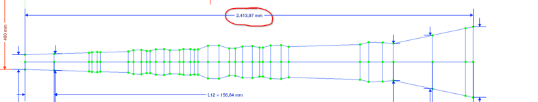
You can adjust some design parameter in order to better match the loudspeaker layout and distentions for a specific driver. Inside the spreadsheet you can only see current values for the dimensions you can change and they are indicated in the group "'Sketch Input values". In order to change their values itself, you need to go to sketch edit mode by double clicking over Sketch in the model tree. Editable parameter are RED colored and they have the same names as the cells in the spreadsheet.
In the website, when you click over any model, you will see their sketches with those red colored dimensions.
Let me know if this is what you was looking for.
Note: While editing sketch dimensions, I suggest to do it by small step, sometimes the CAD software go crazy and breaks the model without any reason. For instance, the current dimension is 400 and you want to change it to 500. It may worth increasing in steps of 25 or 50, it depends model by model.
Amazing! This is fantastic, and easy to understand now you've explained it so clearly. 🙂 I'm off to try out some changes to the dimensions in various models, especially in the Manifold model using the SB Audience driver I've input ... seems to have a falling response after the second resonance peak at 145hz (Manifold is slightly off topic sorry). In any case, the SS sims great and I should hopefully be able to output the 3d model to fusion360 and add the bracing from there if my rudimentary cad skills permit. lolLet me know if this is what you was looking for.
Last edited:
Open a new thread where you can discuss the manifold design and your findings, there are people that are interested in that cabinet layout, it is simple and looks very promising.in the Manifold model using the SB Audience driver I've input ... seems to have a falling response after the second resonance peak at 145hz (Manifold is slightly off topic sorry)
is that a FreeCad bug ?Note: While editing sketch dimensions, I suggest to do it by small step, sometimes the CAD software go crazy and breaks the model without any reason. For instance, the current dimension is 400 and you want to change it to 500. It may worth increasing in steps of 25 or 50, it depends model by model.
i tried with it a lot ( well maybe not enough) and i could not join panels once drawn, i always get the errors... too many constraints, too little constraints and such, could not fully understand how the constraints work and idk if you can get rid of them as in traditional CAD , anyway i tried sketchup again and now i can crank up the 2d plan views and the 3d models,
i know, it it not parametric and you can not do what you can in FreeCad but at least i can make the napking and pen cabinet doodles look decent,
and bring those to a woodworker or CNC Machinist if needed
or help fellow members who have the skills in HR to make their creations look neat.
Cheers.
Below is Art Welter Dual 15" TH for peavey low rider designed in 2008, he called it
B Low Rider
from this
to this
Last edited:
Amazing! This is fantastic, and easy to understand now you've explained it so clearly. 🙂 I'm off to try out some changes to the dimensions in various models, especially in the Manifold model using the SB Audience driver I've input ... seems to have a falling response after the second resonance peak at 145hz (Manifold is slightly off topic sorry). In any case, the SS sims great and I should hopefully be able to output the 3d model to fusion360 and add the bracing from there if my rudimentary cad skills permit. lol
I sounds good. Waiting for your feedback when you able.
The refinements can be done in any CAD, even with Scketchup that is easier them FreeCAD.
i tried with it a lot ( well maybe not enough) and i could not join panels once drawn, i always get the errors... too many constraints, too little constraints and such, could not fully understand how the constraints work and idk if you can get rid of them as in traditional CAD , anyway i tried sketchup again and now i can crank up the 2d plan views and the 3d models,
It looks like mindset issue, probably you are doing wrong things.
Redrawing a full model for sure you are spending much more time compared to FreeCAD model available.
If you find more people interested I could try to make live session to show how it works en clear questions. I've been busy with other subjects, so also slowly I'm forgetting things 😀
Probably, i tried several weeks and even ask in the FreeCad forums but they did not chime in to help, so i guess they are a closed community.It looks like mindset issue, probably you are doing wrong things.
so i started to Hate Freecad for that reason, unlike here that many people chime in and help
I am looking to learn Fusion but the interface is a completely different beast, there is people who use blender also
to get nice 3d models but again it depends on what click on your brain.
what i just find limiting in SketchUp is the way the dimmension tool work, sometimes you cant position or measure something with ease, also you cant measure angles, and text is only scalable when is in 3D, if you use the regular text tool, the font did not scale when you zoom in and out.
plus the fact that i need to export in .skp then import in freecad and export to DXF if i need.
the free version of sketchup do not export in DXF or DWG neither .step
setting aside those minor nuisances it is pretty workable
All CAD software are basically the same. It's like driving a CAD, if you change brand, small things might be different but its still a CAR and you can drive it.
1) If you want to draw a enclosure from scratch it requires some CAD knowledge.
2) If you want to change dimensions from the model I created in FreeCAD, it's very simple and don't require any cad knowledge. You only used mouse double click and numbers keys.
3) If you want to change the model I made in FreeCAD, you will face a lot of issues if you don't master CAD.
I think you are trying the 3) while you should do the 2)
To work with Sketchup you simple export from FreeCAD as Collada *.dae
Marcelo I differ upon your opinion,All CAD software are basically the same. It's like driving a CAD, if you change brand, small things might be different but its still a CAR and you can drive it
i used to use Autocad back in the 90's and to draw blueprints for homes 2D, and you did not need to constrain anything, with freecad you need to constrain everything, and the term CAD is Computer Aided Design , yeah you use a computer but the way the software "AID" you , deviates a lot from one software to another, software companies do not follow a standard on how they will make the GUI nor what functions they will implement just to say some.
IMHO
it is not apples to apples or oranges to oranges
even that you go from point A to Point B
like driving a bike,... a car ... a bulldozer ... or a plane...
you need to have much more different set of skills to maneuver one vehicle or the other
yes ,you "drive" (operate ) them but having the skill to drive a car do not guarantee that you can operate a forklift
or fly a plane.
the only thing that is common in some cases is the file formats like DXF and so on, most of the CAD software can import and export in "popular" formats.
and from i have seen SolidWorks and Fusion have the cuting edge in graphics quality, on sketchup you see the graphics not so refined, Freecad have that "Coarse" quality also, the graphics do not show as clear and precise as Fusion and solidworks, i guess the graphic render module is not as complex as the more expensive counterparts,
My 2 cents.
Ok to differ but you just confirmed the mindset.
Constrains ins't FreeCAD feature, is a feature that some CAD Software has and you can use or not. It's desired when you need parametric drawing, a kind of automation.
Solidwork has more advanced feature compared to FreeCAD, if you work using it you are in a good place. My TH SS15 was designed using Solidwork, a Pirate licence, so I decided to move to Free software and avoid licence issue. If you can Pay for it or Solidedged, they are TOP quality.
Maybe the issue for you isn't CAD overall but parametric drawings. Look for some information about it and it may help you.
Parametric drawings and regular drawings are different mindset.
- Home
- Loudspeakers
- Subwoofers
- 3015LF Enclosure Plans - SS15 with cone correction