i find that a pentode driving 300B can sound as sweet as with triode but the sweet spot for the golden Ratio between H2 and H3 is fun but hard to get just with ears. with the VR tube you can get rid of the Screen bypass capacitor who 's influence on the sound is bigger than the Cathode bypass .
Hello,
That is why in the eighties people start using the we310A/B tubes like in the original Western electric theatre amps.
Greetings, Eduard
That is why in the eighties people start using the we310A/B tubes like in the original Western electric theatre amps.
Greetings, Eduard
You absolutely must not use a choke to load a pentode wired as a pentode.
Gain of a pentode stage is gm*RL, and with a choke your RL will wander all over the place depending on frequency and you will indeed get horrendous sound.
Gain of a pentode stage is gm*RL, and with a choke your RL will wander all over the place depending on frequency and you will indeed get horrendous sound.
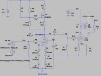
I've redrawn a schematic taking account of suggested mods. Thanks guys.
But just a question about choke loading a pentode.... In an output stage the anode is connected to the OPT which is a wound component. How is this different?
Any suggestions on the revised schematic?
But just a question about choke loading a pentode.... In an output stage the anode is connected to the OPT which is a wound component. How is this different?
Any suggestions on the revised schematic?
Attachments

Andy, 4P1L as pentode requires -at least- 20-25k load, so 40H Hammond choke is very small amount, even 100H LL1668 too.But just a question about choke loading a pentode....
200H is the minimum.
Attachments
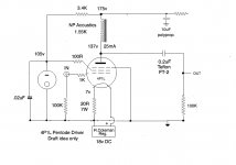
euro21 - Good call on the choke. My best choke (right now on the triode 4P1L stage) is a NP Acoustics amorphous core, gapped for 40mA and 180H. That would work as a choke, yes?
Here's a revised schematic with the NP choke back in.
Also my previous schematic with the anode resistor was way out with the voltages - I calculated for 2.7K anode resistor instead of 27K. Obviously getting tired at the end of the day.
Here's a revised schematic with the NP choke back in.
Also my previous schematic with the anode resistor was way out with the voltages - I calculated for 2.7K anode resistor instead of 27K. Obviously getting tired at the end of the day.
Attachments
Last edited:
I've redrawn a schematic taking account of suggested mods. Thanks guys.
But just a question about choke loading a pentode.... In an output stage the anode is connected to the OPT which is a wound component. How is this different?
Any suggestions on the revised schematic?
the problem is that you need a higher B+ if you want more than the 2,5ma in you schematic 🙂
Andy, one quick question...i remember that you tried IT vs. gyrator boards ...amd now I do not see any plays to go with gyrator boards anymore ? Did you change your mind ?
Because you put 20dB of feedback around an amp like that to nullify the differences and you say a short prayer that the speaker load you have at the output transformer terminals is close to resistive so the reflected load back to the tube is reasonably flat. Then in reality none of this really happens and you take what you can get.But just a question about choke loading a pentode.... In an output stage the anode is connected to the OPT which is a wound component. How is this different?
With a driver pentode tube, you can get a nearly perfectly resistive load by just using a resistor. Yes, there will be some miller capacitance that will factor in at high frequencies, but you have the option of selecting a plate loading resistor to provide an appropriate output impedance to avoid that. For a tube like the 4P1L with decent transconductance, the plate load resistor doesn't have to be all that high. You might also consider bringing the driver B+ way up.
Choke Loading A Pentode
Andy
When you choke load a pentode, you have effectively two constant current sources battling each other. To "settle the peace" look to the work of Gary Pimm. Pimm achieved excellent results when loading a pentode with a CCS by placing a resistor from the junction of the pentode's anode and the bottom of the CCS to ground. This resistor took any variation of current arising so that both the pentode and the CCS behaved themselves with the CCS offering a very high load to the pentode. The result was high gain, low distortion and large swing. The gain was determined by: gm*R where gm is the transconductance of the pentode and R the resistor to ground mentioned above. Now while the choke is not a CCS, it behaves like one, so perhaps it is worth a try put one in a see what results. Reference to Pimm is here:
Audio Asylum Thread Printer
Hope this helps
Tony
Thanks Tony. Pentode stages are completely new to me and this is all very valuable information. I'm starting to see how different pentode stages are from triodes! And I thought at the start of this series of experiments that all I had to do was fit a resister to the screen and a small cap to ground. Ha ha.......
hi andy , if a clumsy french like me could make it everyone can,
looking at these pentode curves ( with 80V G2 but 100V should not be so different) it seems that you could get a lot of swings without too much distorsions with your 27K resistor near 170V at 8ma for -5V bias , the goal is to stay away of the left of the curves. 🙂

looking at these pentode curves ( with 80V G2 but 100V should not be so different) it seems that you could get a lot of swings without too much distorsions with your 27K resistor near 170V at 8ma for -5V bias , the goal is to stay away of the left of the curves. 🙂
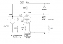
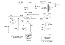
Thanks! I found that I have a few 75v VRs so I've redrawn the schematic with 75v on the screen. Ale also said that there was less distortion around 80v. It could also work with a 6C4C. The thing with the 4P1L is it likes 20mA and above. It sounds thin under that amount of current and definitely not at its best. 18v a la rigeur but less isn't doing it justice. 8mA is not an option.
Attachments
Last edited:
Andy,
fans of the pentode driver prefer that the difference between Ua and Ug2 on driver should be at least equal to the bias on output tube.
This is because the anode voltage swing should not come below Ug2 value, because THD of driver tube then increases dramatically.
Just my 2c.
fans of the pentode driver prefer that the difference between Ua and Ug2 on driver should be at least equal to the bias on output tube.
This is because the anode voltage swing should not come below Ug2 value, because THD of driver tube then increases dramatically.
Just my 2c.
If I can help.
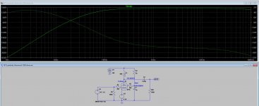
On one of my USB sticks found a 300B SE amp simulation scheme with a 4P1L pentode driver. That was simulated a long time ago when Anatoly showed off his Gubernator with this type of gyrator, as I applied on my 4P1L.
BTW, I'm not a fan of IT or input transformers, unless it's a step-down ratio.
In my simulation: with 2Vrms inputs, Pout = 4.8Wrms and THD = 2.87%.
Best diying.
Attachments
RajkoM: Thanks a lot for that. So for 75v on the screen we need 150v on the anode to comply with the WE operating points for 300b - 350v, 60mA, -74v. I will probably run it a bit cooler than that.
I think this schematic is correct - lots of calculations!
I think this schematic is correct - lots of calculations!
Attachments
Last edited:
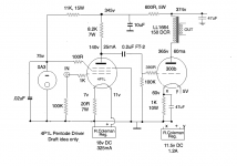
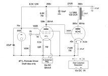
Point y is at 55v, not 5v as labelled.
As originally drawn, the alternative would be that the 1k resistor becomes 22/6 as big, the supply voltage goes up by 160v and you have to dissipate an extra 160v in the step down resistor feeding the lower voltage valve anode. The rod coleman regulator would be floating at ~200v above ground.
Since everyone tells us that the 300b draws grid current before 0v, you could direct couple the (unused) half of the 4p1l as a triode cathode follower and thus provide the hungry 300b grid if the music gets loud.
kind regards
Marek
Last edited:
- Home
- Amplifiers
- Tubes / Valves
- 300B SE with a DHT driver