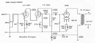
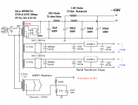
I just finished a 300B amp based on that "first schematic" attributed to JC Morrison and honestly I wasn't impressed. As someone else said, that direct coupled front end farted out at very low drive with weird asymmetrical clipping. It was super sensitive but had no drive for the power tube. Thin bass and the top end was too bright. I rewired it more like that "Time Bandit" example, with a cascode using a voltage divider for the upper section grid and it sounds WAY better with 3X the output. My CD deck/phono stage is plenty capable of driving it with no preamp. I'm sure the 300B can handle even more drive but this sounds nice for a very simple circuit using 6SN7 tubes. Attached is the schematic + power supply using a single transformer setup as a dual rail with regulated DC heaters for the 300B and 50V DC offset on the 6SN7 heaters..
Here is my video series about this build.
300B DIY Budget Tube Amplifier Build Series - YouTube
This video is specifically showing the difference on a scope between the JC Morrison and this other cascode redesign.
Tuning and modifying a JC Morrison style 300B DIY tube amp. - YouTube
Here is my video series about this build.
300B DIY Budget Tube Amplifier Build Series - YouTube
This video is specifically showing the difference on a scope between the JC Morrison and this other cascode redesign.
Tuning and modifying a JC Morrison style 300B DIY tube amp. - YouTube
Attachments

stephe,
Great Video!
That was a successful implementation of a cascode driver for a 300B.
Keep on modifying, measuring, listening, and making videos.
There are lots of newbies and others who will be building now.
Great Video!
That was a successful implementation of a cascode driver for a 300B.
Keep on modifying, measuring, listening, and making videos.
There are lots of newbies and others who will be building now.
3. Now we have a high inductance plate choke we can use an unbypassed cathode resistor up to around 220R. This allows for some flexibility with tube and operating point.
To complete this design use a choke like Lundahl LL1668/10mA or LL1668/15mA. Then try out a variety of drivers in triode, like D3a, C3g, 5A/152, EF810, E280F, EC810, 6e6P, 6e5P, EF184, E180F, EC86, 6S3P, 6C45P...... plenty to try..
Problem with using a tube with unbypassed cathode resistor is that the drive impedance at the plate is affected by (~Rk x mu). So apples with apples, you could drive a 300B with (lets use D3a) ~2400 ohm impedance, or with the example above; (220R x 70 =) 15,400 + 2400 = ~17,800 ohm.
Worse still, you need to add the Xc of that coupling capacitor to that drive impedance.
I dont see how 150H is even suitable as plate load for 18K Rp tube for full range use, the interwinding capacitance is high, so you end up with compromised LF, HF and subsequently a (very) compromised amplifier.
Did you try this and find it acceptable?
I dont see how 150H is even suitable as plate load for 18K Rp tube for full range use, the interwinding capacitance is high, so you end up with compromised LF, HF and subsequently a (very) compromised amplifier.
Did you try this and find it acceptable?
I have tried a variety of drivers for my SE 300b amp, up to around 11K to 13K Rp with a mu around 30-40. So let's say 12K and mu=30. 220R x 30 = 6,600 + 12,000 = 18,600 ohm. My plate choke is amorphous, 180H at 40mA. A very large plate choke. The sound is the best I've heard from any amplifier I've built in 15 years (a lot...). I didn't bother with a bypass cap since the sound was so good. If I had tried a cap it would have been a DC Link, which I use on the cathode of the 300b. I prefer no bypass where possible. Coupling cap is always FT-2 Russian teflon, 0.2uF.
Despite the maths above, the results appear to be fine. I use good bookshelf size speakers, so no really deep bass and I don't listen loud. I'm over 70 so some drop in extreme high treble but otherwise good hearing. Younger listeners have also confirmed the good sound.
.
Last edited:
I have tried a variety of drivers for my SE 300b amp, mostly around 11K to 13K. My plate choke is amorphous, 180H at 40mA. A very large plate choke. The sound is the best I've heard from any amplifier I've built in 15 years (a lot...). I didn't bother with a bypass cap since the sound was so good. If I had tried a cap it would have been a DC Link, which I use on the cathode of the 300b. I prefer no bypass where possible.
Hi,
Which tube and at what operating point and what value of Rk?
I’m trying to work out how you determined drive impedance at 11k to 13k.
I should say I was responding to your suggestion as quoted above at #104 but now I’m even more curious ..
Thanks.
Last edited:
Hi,
Which tube and at what operating point and what value of Rk?
I’m trying to work out how you determined drive impedance at 11k to 13k.
I should say I was responding to your suggestion as quoted above at #104 but now I’m even more curious ..
Thanks.
Thanks for your input. I'm going to pass on naming the driver tubes I'm using for various reasons, but imagine a tube in triode of around 12K Ri, mu 30-40. Imagine a Rk of 200-220R. Va-k would be somewhere around 150v and bias could be anywhere between 1.5v and 3v. Current would be anywhere between 6mA and 10mA. These are the ballpark operating points.
No probs, all I'm trying to highlight is that (from #108) 12k Rp with mu 35 and Rk 210 will have an effective drive impedance of 19,350 ohms. If you use 0.2uF coupling cap, you can add another 795 ohms at 1kHz for over 20k drive impedance, and with that same cap, the drive at 250Hz is over 23k ohms.
With regard to #107, thats much less than the 11-13k unspecified example cited in #106.
Staying now with details at #104, again, D3a will have you at over 18k with unbypassed 220R - and I guess thats my point (outside of any subsequent side-steps), its simply a poor idea.
Unsure the winding C of your plate choke at 180H, but even the Tango 160H units suggest to limit Rp at 10k. 18k and even 1pF of interwinding C is -3dB at < 9kHz. There is also the effect of Xc to drive impedance (as per above) and the example would have over 20k drive impedance (19k at 1kHz, 21k at 250Hz, 34k(!) at 50Hz) into the heavy Cgp of 300B. Which is nuts when you could do it easily with a flat ~2.5k ohm drive impedance using the same plate loaded tube.
Last edited:
Thanks a lot for your calculations. Did you look at Ale Moglia's 300b amp in the link? He uses an active load, and his cathode resistor is 510R, but he has added solid state circuitry.
300B SE Amp: 47 Driver – Bartola(R) Valves
I don't have any measuring equipment, which would be very helpful in answering your questions. I'll have to try inserting a cathode bypass and listening to it. I've made a note of all your calculations. I'm not hearing a compromised frequency response as you suggest, and the amp sounds marvellous, but I need to look further at this.
With regard to the linked amplifier at post #107, yes, please see comment at #109.
And to that, the high value of load impedance and low impedance at the transistor output of the circuit is the complete opposite of the example referenced at #104.
The effect of unbypassed Rk on drive impedance is easy to understand if you consider Zout will be ~ Rp + (mu x Rk).
I didnt have any question except to ask which tube you liked with 18k drive impedance (from your post at #105) - and you declined to answer (#108). Measuring equipment will not help you answer this question, (if thats what you are suggesting in #110), however, you can measure for in-circuit frequency response with a simple AF signal generator and a volt meter.
Some thoughts about singleended Valve Amplifiers by Thorsten Loesch
https://community.fortunecity.ws/rivendell/xentar/1179/theory/seamptheory/SEAmplifiertheory.html"So I think to analyse the Driver / Output Valve interface we MUST take some radical steps. I would suggest a week fasting and abstinence from sex and poisons like Alcohol and Tobacco. Combine this with listening to your favourite Music with your favourite Amplifier and Speaker."
Hmm never done that before critiquing an amplifier, maybe I am doing it wrong?
Hmm never done that before critiquing an amplifier, maybe I am doing it wrong?
- Home
- Amplifiers
- Tubes / Valves
- 300B schematic recommendations