popa marius,
You said: "Direct current can be injected into the secondary to measure the primary inductance, this current must be proportional to the transformation ratio but it is mandatory to use a CCS"
. . . Correct.
1. DC current is necessary not only for the inductance measurement, but also necessary for low frequency harmonic distortion measurement (pick an appropriate low frequency and appropriate signal power level).
Saturation at frequency and power . . . Need to know this, especially if the transformer will be inside of a negative feedback loop;
because the saturation will increase exponentially right after that frequency / power level combination barely starts to saturate . . . as the global negative feedback "correction" will throw even more insulting current at the primary. The more the error, the more current it throws, the more error, the more current, . . . you get the idea.
The proper current is according to the turns ratio.
The Amp x Turns of the secondary has to equal the Amp x Turns of the Primary (equal magnetization of the laminations).
For example 5K to 8 Ohms is 25:1 turns ratio.
A 60mA DC rated primary, if tested by putting DC on the secondary, would be 25 x 0.060A = 1.5A DC into the secondary.
2. I once saw a major good quality transformer manufacturer's data sheet error.
Primary DCR was 0.05 of primary impedance
Secondary DCR was 0.05 of secondary impedance
But the same data sheet listed the insertion loss as 0.5dB
Consider a voltage divider in the primary: 1 / 1.05, that is 0.4dB loss [20 Log (1 / 1.05)]
Consider a voltage divider in the secondary: 1 / 1.05, that is 0.4dB loss
The total loss due to DCR is 0.8 dB, not 0.5dB . . . 0.3dB more loss than the rated 0.5dB.
All of us make mistakes, including top level manufacturers.
"Trust But Verify"
Last edited:

Basically with this device you can set the secondary current between 0-2.5A equivalent 0-100mA in primary for the example given by you (Z=5K, Np/Ns =25) and the load resistance in primary 2.2K-7.2 K. You can also easily check the SQW 10Hz-100Khz signal, frequency band, inductance with and without DC
After some tests I prefer a variable DC power supply 0-60 or 0-100 volt- 2/3 A max with dispaly. More easy to play
With the related components ( as photo)
But this is my approach
At the end of the story a good OT with or without dc current the performances are quite similar.
And this is what I am looking for a good trafo
Walter
With the related components ( as photo)
But this is my approach
At the end of the story a good OT with or without dc current the performances are quite similar.
And this is what I am looking for a good trafo
Walter
using a ccs for measurement above 10kHz needs a better ccs then just a simple fet. Walt Jung wrote some nice articles about ccs for high-end performance measurements.Basically with this device you can set the secondary current between 0-2.5A equivalent 0-100mA in primary for the example given by you (Z=5K, Np/Ns =25) and the load resistance in primary 2.2K-7.2 K. You can also easily check the SQW 10Hz-100Khz signal, frequency band, inductance with and without DC
For SQW measurement there is no need for CCS, basically it is isolated in the device, only the amplifier with the adaptation rheostat in the secondary and the load resistor in the primary remainsusing a ccs for measurement above 10kHz needs a better ccs then just a simple fet. Walt Jung wrote some nice articles about ccs for high-end performance measurements.
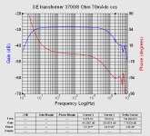
Some lab test with a KT88 in triode mode gain 7 time, one stage without any driver
6 Vin from AP
Vdc around 390 volt
Ia between 50 mA to 100 mA
50mA red bottom
60 mA cyan
70 mA green
80 mA yellow
90 mA red
100 mA violet

until 80 mA the response is very good and compliant with the reverse mode
6 Vin from AP
Vdc around 390 volt
Ia between 50 mA to 100 mA
50mA red bottom
60 mA cyan
70 mA green
80 mA yellow
90 mA red
100 mA violet
until 80 mA the response is very good and compliant with the reverse mode
Last edited:
I wrote a wrong value of inductance.
Due my misunderstanding with the guy who wound the trafo the exact value at 100 Hz is 40 H
This is the first value I put on post days ago then modified
Excuse
Walter
Due my misunderstanding with the guy who wound the trafo the exact value at 100 Hz is 40 H
This is the first value I put on post days ago then modified
Excuse
Walter
The phase

With a differential probe the response on primary (top) with some resonance at 200 kHz and a little step on 100kHz
and secondary ( on the load, 7,5 ohm )

With a differential probe the response on primary (top) with some resonance at 200 kHz and a little step on 100kHz
and secondary ( on the load, 7,5 ohm )
Yes, but you need it for the other measurements. We will see what Walter has to ofer us, i hope he calmed down.For SQW measurement there is no need for CCS, basically it is isolated in the device, only the amplifier with the adaptation rheostat in the secondary and the load resistor in the primary remains
Maybe some sqw measurements at 1kHz and 10kHz
Last edited:
Nice measurements WalterSome lab test with a KT88 in triode mode gain 7 time, one stage without any driver
6 Vin from AP
Vdc around 390 volt
Ia between 50 mA to 100 mA
50mA red bottom
60 mA cyan
70 mA green
80 mA yellow
90 mA red
100 mA violet
View attachment 1323662
until 80 mA the response is very good and compliant with the reverse mode
I guess about 0,5W output power.
In post 1 you posted that is is a 3000/5 Ohm transformer. It would be nice to use this 5 Ohm at the secondary and not with 7,5 Ohm as you did now.
Just minor details....
Just minor details....
The reason of the 5 ohm is to delivery more current at the real load where the modules is variable mainly in the bass region where it goes down ( and up specially in bass reflex) and the energy is great
Possibly with less Thd
In this way the Z on primary stay with a good range of value
The test are done with 7,5 ohm as standard for me
Possibly with less Thd
In this way the Z on primary stay with a good range of value
The test are done with 7,5 ohm as standard for me
I understand your point but you measure at 4500/7,5 Ohm transformer now. And this is good but different but not consistant.
The downsite: you will have saturation problems.
The downsite: you will have saturation problems.
I check the 7,5 ohm and 5 ohm load; Vdc 380 V, Ia 70 mA, KT88 Triode
At 50 hz the Z is ( on live circuit)
7,5 ohm = around 5 kohm,
5 ohm = around 3500 ohm
Safe
I ahve also tested the Z on different level at 50 Hz, with Rl=5 ohm
with
68 volt around 3300 ohm
With 7,5 ohm the results are better but similar
The THD stay around 2,2-2,5 %, no sign of saturation
68 Vac on primary; 5 ohm load, 50 Hz

Freq. response
The difference on level is around - 0,8 dB for 5 vs 7,5, same shape of curve

I am preparing the final setup to go in deep
Walter
At 50 hz the Z is ( on live circuit)
7,5 ohm = around 5 kohm,
5 ohm = around 3500 ohm
Safe
I ahve also tested the Z on different level at 50 Hz, with Rl=5 ohm
with
68 volt around 3300 ohm
With 7,5 ohm the results are better but similar
The THD stay around 2,2-2,5 %, no sign of saturation
68 Vac on primary; 5 ohm load, 50 Hz
Freq. response
The difference on level is around - 0,8 dB for 5 vs 7,5, same shape of curve
I am preparing the final setup to go in deep
Walter
Attachments
Walter,
"The THD stay around 2,2-2,5 %, no sign of saturation
68 Vac on primary; 5 ohm load, 50 Hz"
Of course no signs of saturation (transformer or tube cut-off). For that you have to go down to 20Hz and/or make the signal bigger (you are now between 0,5W and 1W) but if you do so, yes it will do so. No worries, physics still stay the same as always.
And 1 more question: post 1 was 3000 Ohm / 5 Ohm and now it is again different. Please don't switch all the time (if you want a reliable person with a reliable transformer) What are the specifications of your transformer now?
Last edited:
Walter,
Sorry for just seeing this tread. Looks like you have a real winner on your hands.
I just shipped a Triton Silver Signature 300B amp 2 weeks ago. That had %99.999 pure silver, teflon wound by MagneQuest. Now that we lost Mike, I only have a few pairs of these left. They are a variation of the FS030 which is 3K: 4/9/16 wound with Peerless 3 separate secondary method of series parallel. The FS030 was like 48H @ 60ma, in the Triton which at 5% did 12.5W and 10% did 14W @ 1KHz, I was running the 300B at 75ma and 400V. At 75ma in Silver the L was more like 41H. Sorry I didn't save the dScope III outputs for that amp. Just did a verify and then listening tests before it went out. Mike always said that potting outputs was bad unless done with bees wax as the core would be restrained.
As a guitar player I can tell you potting pickups seems to drastically change the character of the sound. I have some silver Tele pickups in my Esquire that Seymour Duncan made for me and they are unpotted. I have 3 other Teles with various Fralin and Lollar pickups that are potted and not potted. Everything makes a difference in sound.
Anyway keep me up to date, your results look really good so far.
Thanks,
Gordon
Post 1 was on first protoAnd 1 more question: post 1 was 3000 Ohm / 5 Ohm and now it is again different
This is the second with different architecture and coils
Differences (little) are normal or not?
Then read the final words of my post
Walter,
May I advice not to pay attention to Ternopil's posts; you best put him on your ignore list because he has nothing positive to contribute but just waiting for you to get frustrated.
You are right in your assumption about his identity....yes the same guy banned here some five times before.
May I advice not to pay attention to Ternopil's posts; you best put him on your ignore list because he has nothing positive to contribute but just waiting for you to get frustrated.
You are right in your assumption about his identity....yes the same guy banned here some five times before.
- Home
- Amplifiers
- Tubes / Valves
- 300B OT nano, first test