Thank's a lot John!! for your time, and your work.Hi Moorclos
Ivé simulate some new re-built xover for your Jamo 707 in XSim, based on your orginal filter/xover. (Based on your original xoverparts)
The XSim xover that you had in your last post had very low impedance, and no woofer curves.
This xover match crossover-points better at both 150 and 2.500 hz, and just to show you i used 2 x Peerlees 830667 (to get something to work with)
You can use most of your "orginal xover parts" for example you can un-wind the 5,3mH coil in the midrange down to 4mH.
Borrow a LCR meter if you dont have one!
ANd remember....The Peerlees woofer in XSim was just an example!
Best regards John
I am going to look closer to this.
(have a LCR meter since 1 week 😉 )
Best regards Laurent
PS: Very good new Response in SPL and Impedance, far away than before!!
(change the 5.3mH coil in the midrange is an obligation?)(I imagine for better impedance? --no easier solution?)
Last edited:
PS: Very good new Response in SPL and Impedance, far away than before!!
(change the 5.3mH coil in the midrange is an obligation?)(I imagine for better impedance? --no easier solution?)
You can try it first with your 5,3mH !
If you use 5,3mH the simulatin show xover-point goes down to 120 hz, and a little 2-3dB raise in dB around 120-200 hz nothing else!
/John

And your Fenton 8 woofers seems to work fine after small calculations.
The closed/sealed one have about 16 liter to work in, and the other about 30 liter to work in as a reflex.
My small calculations show 30,65 liter in reflex solutions, so thats perfect!
Sadly i can´t calculate closed/sealed boxes.....But it always use to be smaller boxes then reflex....So 16-17 liter will be fine i think.
But i can´t find any curves on the Fenton woofer
/John
Attachments

Ty! John,And your Fenton 8 woofers seems to work fine after small calculations.
The closed/sealed one have about 16 liter to work in, and the other about 30 liter to work in as a reflex.
My small calculations show 30,65 liter in reflex solutions, so thats perfect!
Sadly i can´t calculate closed/sealed boxes.....But it always use to be smaller boxes then reflex....So 16-17 liter will be fine i think.
But i can´t find any curves on the Fenton woofer
/John
(For closed and sealed box, in winisd I think, we should use 1 pair isobaric 4th band, and put the volume of the rear box(closed?) And the front one (reflexed?)) So we may calculate it, event if the closed one is seal
Ty! John,
(For closed and sealed box, in winisd I think, we should use 1 pair isobaric 4th band, and put the volume of the rear box(closed?) And the front one (reflexed?)) So we may calculate it, event if the closed one is seal
I have no skills in winisd, and always have trubble putting in "parameters"...Get errors! ( fdr files often works)
Also winisd dont help you/us to build a xover for the woofers.
But i know 30 liter in reflex is perfect for your Fenton woofer, and you can´t do anything about the 17 liter sealed...It is what it is 👍
/John
Ok I understand better now your considerations. Thx,I have no skills in winisd, and always have trubble putting in "parameters"...Get errors! ( fdr files often works)
Also winisd dont help you/us to build a xover for the woofers.
But i know 30 liter in reflex is perfect for your Fenton woofer, and you can´t do anything about the 17 liter sealed...It is what it is 👍
/John
/Laurent
My calculations goes like this in reflex-box regarding to calculate box-liters
VAS value on your Fenton is 27,789 liters, and Qts value is 0,447
The calculations become VAS x Qts x Qts x 5,7....As in 27,7 x 0,44 x 0,44 x 5,7 = 30,56 liter
Simple and quite correct most times.
/John
VAS value on your Fenton is 27,789 liters, and Qts value is 0,447
The calculations become VAS x Qts x Qts x 5,7....As in 27,7 x 0,44 x 0,44 x 5,7 = 30,56 liter
Simple and quite correct most times.
/John
😵 seems to be great performance for a home-speaker, 30hz -5db!And in winisd it looks like you need a 11 cm port 70mm if you want to tune it at 50 hz 14dB down at 30 hz
28 cm 70 mm port if you want to tune at 35 hz, and only 5dB down at 30 hz
/John
Thx again John.
/Laurent
PS:
- do you know on your thermistor, the value of the resistance for it (a thermistor act as a resistor in some maner no?)
Feels like something is not right with your posted Fenton winisd file!😵 seems to be great performance for a home-speaker, 30hz -5db!
Thx again John.
And when i look at upper left corner in program it says "winisd ERROR ??
Maby my simulations wasen´t right, and in winisd it falls of so much after 30 hz ?
Havent workt with isobaric 4th band either, so don´t know how the curves supose so look like.
And im not good using winisd
PS:
- do you know on your thermistor, the value of the resistance for it (a thermistor act as a resistor in some maner no?)
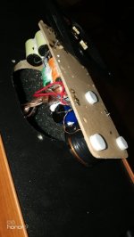
I took the thermistor away in my modified Jamo original xover, i think its only a voltage-protection/overcurrent protection for the orginal drivers.
It´s a 9 watt max thermisor called PTC C975, and i post a picture!
But now the drivers 5FE120-8 and SB26ADC are much "stronger", so no need for a thermistor.
Best regards John
Attachments
Ok Jawen, thx for these informations on thermistor(I thought the first Time, that this protection act as a resistor in // in some way).
For the winisd simulation effectively it s strange I look at this evening.
(What soft do you use for subwoofer sim?)
I read too, that it s easy to make mistakes with winisd.
For the winisd simulation effectively it s strange I look at this evening.
(What soft do you use for subwoofer sim?)
I read too, that it s easy to make mistakes with winisd.
(What soft do you use for subwoofer sim?)
I read too, that it s easy to make mistakes with winisd.
I hardly build subwoofers, but use Winisd when i do.
But most have WDR files
//john
So now i have re-build both Jamo original xovers, and will write down the things needed and how the work is done.
I will do a final listening and mesauring, but here are what come out of it until this day.
I have in this DIY considered all different things/values/cost and have made a big attempt keeping so much orginalparts as possible on the xover.
Orginal xover board is mounted on the back of the speaker bindingposts, and can be unfolded when you loosen the 4 screws of the speaker-connection-plate.
It isen´t big so you have to use smaller parts like MKT caps and coils maximun 20mm thick but mount the coil standing ( the coil in my recomendation is 15 mm thick and 43mm in hight = no problem.
What you have to buy:
2 X 15uF caps
12uF cap
one 1 mH coil
2,2 ohm resistor
This is for 1 speaker so you need times 2 !
All cost about 20 Euro in total
And buy smaller type caps like Jantzen MKT ( the yellow one) and thin ordenary coils like jantzen audio air core wire 0,72 ohm wire 0,8 mm
https://blackdotaudio.eu/capacitor-...ent---mkt---oval---l-30x24x17mm,202,9302.htmlhttps://blackdotaudio.eu/air-core-w...0-720ohm---wire-0-80mm---43x15mm,67,5759.htmlhttps://blackdotaudio.eu/resistor-m...2---10w-5procent-mox-rss-8-5x53,211,9541.html
Thats all !
Work on the xover:
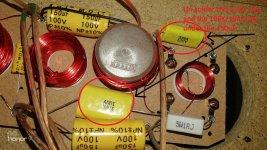
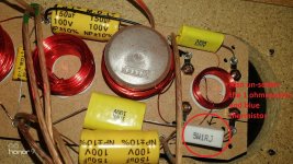
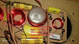
1) Un-solder the 3,3uF/335K cap and the 10uF/106K uf cap under the 150uF cap, but try to keep the 150uF cap still in place by holding it down.( markt in pic xover 1)
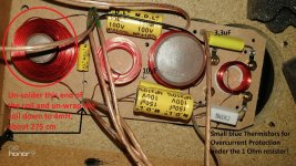
2) Un-solder the 1ohm resistor and also the thermistor on + side tweeter1 ( pic xover 2)
3) Use a razorblade-knife and cut under the 0,7mH coil so it come loose, and un-solder the coil and 10uF cap ( pic xover 3)
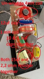
4) Un-solder this side of the big 5,1mH coil, and un-wrap the coil down to 4mH....It´s about 275 cm copperwire that you have to take of in length, ( pic xover 4)
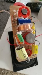
5) Solder the new 12uF cap where the 10uf has sat before across the now 4 mH coil. ( Pic xover 5)
6) Solder the new 1mH coil standing there before the 0,7mH coil was (cut the plastic end so i get flat at downside) ( Pic xover 5 )
7) Solder both 15uF caps and new 2,2 ohms resistor together to be 30uF, and solder it there the old 1 ohms resistor and thermistor have been before.
( Pic xover 5 )
8) Take the 10uF/106K and the 3,3uF/335K as you un-solder before and solder it together as 13,3uF and, then solder it where the 3,3uF/335K sat before
( Pic xover 5 )
DONE !
As you can see on the pic xover 5 is that the xoverboard is quite slim and hole at the back of the speaker is also small/slim, and non of the components can go over the sides, because if it does the board will don´t go back again.
On my pic xover 5 you can see i use 133uF insteed of the orginal yellow 150uF, and did that to get the impedance up a little bit but its not necessary.
I just what to mentioned it, so you don´t think anything is wrong!
A pic xover 5a just to show more!
Ask questions if you have any.
Best regards John
I will do a final listening and mesauring, but here are what come out of it until this day.
I have in this DIY considered all different things/values/cost and have made a big attempt keeping so much orginalparts as possible on the xover.
Orginal xover board is mounted on the back of the speaker bindingposts, and can be unfolded when you loosen the 4 screws of the speaker-connection-plate.
It isen´t big so you have to use smaller parts like MKT caps and coils maximun 20mm thick but mount the coil standing ( the coil in my recomendation is 15 mm thick and 43mm in hight = no problem.
What you have to buy:
2 X 15uF caps
12uF cap
one 1 mH coil
2,2 ohm resistor
This is for 1 speaker so you need times 2 !
All cost about 20 Euro in total
And buy smaller type caps like Jantzen MKT ( the yellow one) and thin ordenary coils like jantzen audio air core wire 0,72 ohm wire 0,8 mm
https://blackdotaudio.eu/capacitor-...ent---mkt---oval---l-30x24x17mm,202,9302.htmlhttps://blackdotaudio.eu/air-core-w...0-720ohm---wire-0-80mm---43x15mm,67,5759.htmlhttps://blackdotaudio.eu/resistor-m...2---10w-5procent-mox-rss-8-5x53,211,9541.html
Thats all !
Work on the xover:
1) Un-solder the 3,3uF/335K cap and the 10uF/106K uf cap under the 150uF cap, but try to keep the 150uF cap still in place by holding it down.( markt in pic xover 1)
2) Un-solder the 1ohm resistor and also the thermistor on + side tweeter1 ( pic xover 2)
3) Use a razorblade-knife and cut under the 0,7mH coil so it come loose, and un-solder the coil and 10uF cap ( pic xover 3)
4) Un-solder this side of the big 5,1mH coil, and un-wrap the coil down to 4mH....It´s about 275 cm copperwire that you have to take of in length, ( pic xover 4)
5) Solder the new 12uF cap where the 10uf has sat before across the now 4 mH coil. ( Pic xover 5)
6) Solder the new 1mH coil standing there before the 0,7mH coil was (cut the plastic end so i get flat at downside) ( Pic xover 5 )
7) Solder both 15uF caps and new 2,2 ohms resistor together to be 30uF, and solder it there the old 1 ohms resistor and thermistor have been before.
( Pic xover 5 )
8) Take the 10uF/106K and the 3,3uF/335K as you un-solder before and solder it together as 13,3uF and, then solder it where the 3,3uF/335K sat before
( Pic xover 5 )
DONE !
As you can see on the pic xover 5 is that the xoverboard is quite slim and hole at the back of the speaker is also small/slim, and non of the components can go over the sides, because if it does the board will don´t go back again.
On my pic xover 5 you can see i use 133uF insteed of the orginal yellow 150uF, and did that to get the impedance up a little bit but its not necessary.
I just what to mentioned it, so you don´t think anything is wrong!
A pic xover 5a just to show more!
Ask questions if you have any.
Best regards John
Attachments
Last edited:
Forgot the important :
You need to fix/peg down the components on the xover-board so they can´t shake and vibrate when playing...( you really hear that when playing high volymes)
May use melting glue or ordenary Latex, but really fixate all the Caps/coils/resistors to the board properly.
One more thing is that the ogrinal thin xover mdf-board ( where all parts sits) is weak as hell and elongated, and you can´t make it stronger by glue some more thin mdf-board on it...Because then it will not fit in the hole.
So this was my solution for the problem.
I take 3 small furniture paw protection pads on top of eachother ( 7-8 mm in total height) in 3 different possitions at the backside of the xoverboard begore i put it back.
Then the pads will met the inide of the cabinette and suport the xover-borad from vibrate.
Best regards John
Attachments
The tip to reinforce the plate is great.
As well as to have allowed to use the original xover, with the minimum of investment, for a maximum of result.
It's a great work! which I hope will allow the lovers of these speakers to enjoy them for a long time.
Sincerely, thank you for the work done, John, (as well as for the help provided by Ray).
Knowing that it is not finished 😉 (finalized xover schematic - final test measurement posts)
Nice work! So this is it? Done? Feels pretty straightforward if i print out the instructions
Still think there is more to win on inproving the cabinet,there are vibrations if you play loud and put your hand on the side, mill out the baffle around the mids and make a new one,is there any benefit to put the tweeter on top as many other speakers have it?
Still think there is more to win on inproving the cabinet,there are vibrations if you play loud and put your hand on the side, mill out the baffle around the mids and make a new one,is there any benefit to put the tweeter on top as many other speakers have it?
Thank you.Nice work! So this is it? Done? Feels pretty straightforward if i print out the instructions
Still think there is more to win on inproving the cabinet,there are vibrations if you play loud and put your hand on the side, mill out the baffle around the mids and make a new one,is there any benefit to put the tweeter on top as many other speakers have it?
Yes this is it !
I have probably spend around 400 hour´s in total with this tweaking/measurement/simulation "thing", and it´s real complicated in several different way´s on this speaker/xoverboard, especially since I want the speaker to look completely original.
Still think there is more to win on inproving the cabinet,there are vibrations if you play loud and put your hand on the side
Belemakare:
We using ONE 8 inch woofer in this speaker, and with the elliptical shape with in the design 2 layers cabinette, we are good 👍
And i have own about 20 speakers so far in my life, and probably listen to more then 500 different one´s at shsop/show and at hifi-friends houses.
ONE time have i come across a speaker that don´t t vibrate when you play loud...ONE time!
It was in my own house with my own Revel Ultima Salon around year 2001-2004, and it weight 110 kilo each with 3 x 8 inch woofer per side and had extra panels on the sides in the design.
To weak cabinetts are one thing, but this is not the case here with the Jamo.
Best regards John
Jawen, please,
may you upload again:
FRD + ZMA to use for the 3 drivers
and your *.dxo
I simulate, but don't find same results (perhaps my files are corrupt)
Thank's
/Laurent
may you upload again:
FRD + ZMA to use for the 3 drivers
and your *.dxo
I simulate, but don't find same results (perhaps my files are corrupt)
Thank's
/Laurent
I simulate, but don't find same results (perhaps my files are corrupt)
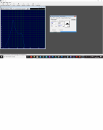
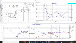
Hi Laurent
Your simulation should look like this.
I have take the woofers of in the simulation because we dont have any woofers FRD or ZMA files, but it dosen´t affect the response from 200 hz and up.
And i use the real in box mesaurements for both SB26ADC and 5FE120-8 midrange, posted before.
Best regards John
Attachments
- Home
- Loudspeakers
- Multi-Way
- 3 way upgrading Jamo D590 replacements and filter question