Measurements and sims tricky to get ultimate agreement. But it should be quite possible to get a reasonable match.
One subtlety is phase, and for the mid tweeter arrangement, ideally with the microphone on the tweeter axis at at a fixed distance, then without moving the microphone the mid woofer response. As the midwoofers are symmetrical around the tweeter one measurement should allow you to use the same measurement for both??. I haven't actually done this and verified if there are any small irregularities due to differing heights of the two Mids. I would imagine its a fairly low order difference, but i could be wrong on that.
You could try swapping the tweeter phase. Definitely worth a try.!!!
Possibly if you have these bits handy with the Mid section reverse polarity on the drivers you could try for the mid crossover just two componets 820uH and 15uF on the mids ( don't forget the reverse polarity )
For the tweeter 11uf first with 22uf on the other side of the inductor or the nearest values you have and 220uH. That should do something I have used your FRD and ZMA files so it should be near.
Thanks for the beer info I will have to try to get some via a supplier here.
Have a rest enjoy the beer. 🙂
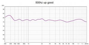
Don´t think im going to do much better than this from 500hz and up?.....1/3 smooting in REW!
Still is shifting only the 3 caps as I previously suggested a very easy smart thing, but if you want to take it farther and have some skills you can do a bigger re-build of originalfilter, and get out even more from the 5FE120 & SB26ADC
This "bigger"diy from orginal Jamo filter is made by a few new parts and unwind 1 coil ( 8,67 mH at the end of filter down to 4 mH) and wind/ wrap on the 0,59 mH coil to 1 mH.
2 x 15uF caps=30uF over 1 ohm resistor, and shift opposite side 3,3 ohms cap (335K cap) to 15 uF.
Take the 150 uF electrolyt cap (on the 1 ohm resistor-side) and replace it with a 100uF cap, and put that 150 uF electrolyt cap (which you removed) "over" "the other" 150uF cap on the opposite side and make it 300uF.
Shift the 10uF electrolyt cap with a 12 uF poly-cap.
Now focus on under 500 hz, and gladly take help from you guy´s.....raymondj hahaha 😉 🥳
As you can see XSim show a terrible spl curve, but real measaurement is real good 👍
Cheeeeers !
Best regards John
Attachments

Really nice work in progresse Jawen.
Here - 1 side/changed: bass have really more body now (2 incoming)


Here - 1 side/changed: bass have really more body now (2 incoming)
Attachments
Last edited:
Im sorry raymondj, i diden´t see your last post until i send my own post ( you probably need to refresh the page to see new posts)
You have as much knowledge as I do not have, and I try to absorb that knowledge but it is difficult sometimes, but so greateful for all you´r help and always posetive words 🤗
You wrote 820uH and 220uH.....What is value uH ?? 🤔
Just know uF and nF.
Moorclose:
Yeaaa no we are talking 💪
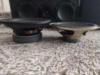
That woofer look´s mean even if i never heard about the brand Fenton....Original woofer looks like a baby dwarf.
Have done some mesaurements from 40 hz now, and it´s not to bad down to 100hz (just a +2-3 dB rise at 350hz)
But knowledgeable people say´s it hard to mesaure under 200hz, so maby it´s better to listen with your ears (or something)
Will try some close up mesaurements on the woofer, and come back to you.
My 4 beer now, and everything goes more with ease 😁
Cheers and best regards John
You have as much knowledge as I do not have, and I try to absorb that knowledge but it is difficult sometimes, but so greateful for all you´r help and always posetive words 🤗
You wrote 820uH and 220uH.....What is value uH ?? 🤔
Just know uF and nF.
Moorclose:
Yeaaa no we are talking 💪
That woofer look´s mean even if i never heard about the brand Fenton....Original woofer looks like a baby dwarf.
Have done some mesaurements from 40 hz now, and it´s not to bad down to 100hz (just a +2-3 dB rise at 350hz)
But knowledgeable people say´s it hard to mesaure under 200hz, so maby it´s better to listen with your ears (or something)
Will try some close up mesaurements on the woofer, and come back to you.
My 4 beer now, and everything goes more with ease 😁
Cheers and best regards John
Attachments
Ahh,... Okey raymondj ivé learning from you....Was thinking about that but diden´t find a example when i made a Google search.
Stupid me !
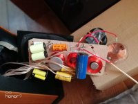
Hard to make woofer mesaurements when hole speaker-binding-post is unmounted, and a big "hole" is there at the back hahaha
What luck that I realized it after only about 10 minutes, otherwise i could have spend much time on the xover 😉
Best regards John
Stupid me !
Hard to make woofer mesaurements when hole speaker-binding-post is unmounted, and a big "hole" is there at the back hahaha
What luck that I realized it after only about 10 minutes, otherwise i could have spend much time on the xover 😉
Best regards John
Attachments
Had a hangover yesterday, a neighbour invited me to his garage/mancave and he have 3 old 1970 musclecars and lots of beer hahaha
Refuse to grow old in my head 😉
But today i continued with the project, and was going mad because the woofers responce on measaurements was so strange and weak.
Try different microphone placements, different mic high....nothing i did change things more then little!.
So eventually i unskrew the speaker-binding-post/xover again....and possetive woofer cable had come loose 🙄
Made me happy to see, because it´s so tight between solder-points and xover-components, so i had begain thinking something major is wrong here.
And also real tight putting the speaker-binding-post/xover in again, so dident know if something had happend.
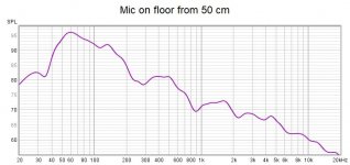
This is mesaurements with the microfone at the floor at about 10cm of high, 50cm in front of the speaker.
Only done 2-3 mesaurements, and will do a few more.
And i have to little experience in measaurements and especially woofer-measaurements up to about 200hz.
Does this look´s okey folks/raymondj ?
Best regards John
Refuse to grow old in my head 😉
But today i continued with the project, and was going mad because the woofers responce on measaurements was so strange and weak.
Try different microphone placements, different mic high....nothing i did change things more then little!.
So eventually i unskrew the speaker-binding-post/xover again....and possetive woofer cable had come loose 🙄
Made me happy to see, because it´s so tight between solder-points and xover-components, so i had begain thinking something major is wrong here.
And also real tight putting the speaker-binding-post/xover in again, so dident know if something had happend.
This is mesaurements with the microfone at the floor at about 10cm of high, 50cm in front of the speaker.
Only done 2-3 mesaurements, and will do a few more.
And i have to little experience in measaurements and especially woofer-measaurements up to about 200hz.
Does this look´s okey folks/raymondj ?
Best regards John
Attachments
In terms of bass its a case of one mans meat is another mans poison.
Is your response with the Bass filter in place and where you plan to use the speakers ?
It looks like you have max bass at 60 Hz falling after that. The other side of the bass response starts rolling off at approx. second order at 150hz or so.
AS you point out bass in rooms is tricky as you may have a suck out at the LF crossover frequency when measured on tweeter axis.
Within that I would do some measurement's on axis and get a feel for the 60 Hz bump and how it effects the room. Alternatively you will see a completely set of results, that differ from your ground plane measurement, with differing peaks and troughs as the room joins in.
Whilst doing this look also look for any disturbance of the midrange as you may find the bass interacting and messing up the flatter mid response. Play with the simulation altering the bass rollover to show you how it could affect the mid. Also swap phase on the bass in Xsim to show you what could happen if you inadvertently swap phase. We have all done that as well !!! 🙂
If you do not judge the bass to be great, you may have to purposely come away from your LF design frequency for the crossover and live with a bit of a dip. Your ears are one of your best tuning tools for this.
Use some well known tracks with bass that you like, and make sure you do not have too much.
Take it easy, these things take time and I am sure you will need a few more iterations.
Thank you for you answer raymondj
Im a man that like quite bass-strong speakers even if off course the bass have to be in "good enough quality ", because in my mind you can always place the speaker so the bass get as strong as you like.
But bass-weak speakers you can´t do "anything" much with.
And Yes, the Bass filter is in place and the speaker stand approximately where it will be used +- 20cm ( the xover based on orginal xover)
Have done many mesaurements from 1 speaker from different mic positions( up to 2,5 meter apart), and over 300hz its quite good everywhere. in the room.
But i haven´t re-built that speakers bass-reflex-port yet, so it is still original short port
And i haven´t re-build the inside filling either, so still original filling inside that test speaker.
Don´t know how much these 2 things will do, but the other/left speaker is totaly re-build but don´t have any xover finished yet.
But will solder it together soon now when im happy with the testresult., and then i can mesaure both original inside filling and original port against re-build filling and port.
Can´t swap phase on the bass in Xsim, because something is wrong.
Sadly It´s not possible for me to use XSim´s since saturday ( when i notice the huge difference from simulation compared to real measurements)
Something in XSim is not right in terms of components-values, and probably coil´s-values ( also begain to doubt ZMA and SPL files, because something is wrong in XSim)
I have masaured the 4 coils 3 times on different day´s...and i get different values on the 2 big coils!
Smallest one seems to be 0,47mH in original tweeter-xover every time i masaure it, also the other small midrange-coil masaure 0,7mH every time.
BUT!...The 2 bigger coils "trick" my LCR meter somehow, and shows values fron 5,1mH up to 7-8,6mH so im lost!
Can´t use XSim without correct values, so most of saturday´s twaeking on xover was done after mesaurement and "trial and error".
raymondj:
Can you have a coil in place on the xover when you masaure the coil ?
And the original xover-board is real small to work with, and the pre-done solder-holes for components makes it difficult.
Thats why i diden´t soldered off the coils before LCR meter measurements
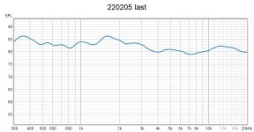
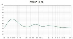
This last measurement is from mic in my sofa at about 3,3 meters distance, -+0,4 meters from my listeningpoint.
Best regards John
Im a man that like quite bass-strong speakers even if off course the bass have to be in "good enough quality ", because in my mind you can always place the speaker so the bass get as strong as you like.
But bass-weak speakers you can´t do "anything" much with.
And Yes, the Bass filter is in place and the speaker stand approximately where it will be used +- 20cm ( the xover based on orginal xover)
Have done many mesaurements from 1 speaker from different mic positions( up to 2,5 meter apart), and over 300hz its quite good everywhere. in the room.
But i haven´t re-built that speakers bass-reflex-port yet, so it is still original short port
And i haven´t re-build the inside filling either, so still original filling inside that test speaker.
Don´t know how much these 2 things will do, but the other/left speaker is totaly re-build but don´t have any xover finished yet.
But will solder it together soon now when im happy with the testresult., and then i can mesaure both original inside filling and original port against re-build filling and port.
Can´t swap phase on the bass in Xsim, because something is wrong.
Sadly It´s not possible for me to use XSim´s since saturday ( when i notice the huge difference from simulation compared to real measurements)
Something in XSim is not right in terms of components-values, and probably coil´s-values ( also begain to doubt ZMA and SPL files, because something is wrong in XSim)
I have masaured the 4 coils 3 times on different day´s...and i get different values on the 2 big coils!
Smallest one seems to be 0,47mH in original tweeter-xover every time i masaure it, also the other small midrange-coil masaure 0,7mH every time.
BUT!...The 2 bigger coils "trick" my LCR meter somehow, and shows values fron 5,1mH up to 7-8,6mH so im lost!
Can´t use XSim without correct values, so most of saturday´s twaeking on xover was done after mesaurement and "trial and error".
raymondj:
Can you have a coil in place on the xover when you masaure the coil ?
And the original xover-board is real small to work with, and the pre-done solder-holes for components makes it difficult.
Thats why i diden´t soldered off the coils before LCR meter measurements
This last measurement is from mic in my sofa at about 3,3 meters distance, -+0,4 meters from my listeningpoint.
Best regards John
Attachments
Measuring in circuit is less than ideal, and as you are seeing can lead to confusion as you you may well see the influence of the interconnected components. This will be dependant on the type of circuit being measured as well. i,e. Other parallel components
Slightly strange that you can get different readings.
Were they different configs, with and without drivers connected for example? Is it time for a new battery in the LCR meter if it is a battery powered device??
Response looks workable.
Ideally you need to get these variables out of the picture and get back to sensible and repeatable results.
I would back up your Xsim data to a USB stick or some such, and de install and then re install Xsim as a quick fix to see if you can get that behaving as it should.
Yes i know raymondj, but it´s so tricky to un-solder one of the coils from the original xoverboard.
I´ve shift 2 of the coils to new ones with known values ( 1mH and 4mH), and the small tweeter coils is stable at 0,47mH
And the "mysterious tricky to un-solder" coils now measuring 2,9 mH ( for the 4th time even if it´s stilll on the board, so maby that value is right)
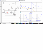
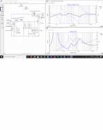
Here is a pic from my XSim with these values entered as i have it right now.
Xover points shown in XSim is 165hz and 2500hz (165hz is a little high)
But look at the impedance, it can´t be right!
My Onkyo reseiver would never have managed 1,33 ohms load in 10-20 measurement ( as XSim say´s), so something is strange here.
The real measurement i did also shows much better spl curve than XSim simulation shows?
Will try to do as you suggest raymondj, put everything on a USB stick and re install XSim
And it´s so lomg time now sinse i made the ZMA/SPL files, so i don´t remember if i use the actual measurement SPL curve for the mid and tweeter!
Best regards John
I´ve shift 2 of the coils to new ones with known values ( 1mH and 4mH), and the small tweeter coils is stable at 0,47mH
And the "mysterious tricky to un-solder" coils now measuring 2,9 mH ( for the 4th time even if it´s stilll on the board, so maby that value is right)
Here is a pic from my XSim with these values entered as i have it right now.
Xover points shown in XSim is 165hz and 2500hz (165hz is a little high)
But look at the impedance, it can´t be right!
My Onkyo reseiver would never have managed 1,33 ohms load in 10-20 measurement ( as XSim say´s), so something is strange here.
The real measurement i did also shows much better spl curve than XSim simulation shows?
Will try to do as you suggest raymondj, put everything on a USB stick and re install XSim
And it´s so lomg time now sinse i made the ZMA/SPL files, so i don´t remember if i use the actual measurement SPL curve for the mid and tweeter!
Best regards John
Attachments
Hallo guy´s
Finally, things get a little logical regarding to XSim, values and mesaurements !
Today i begain "from the begaining", mesauring tweeter and midrange mounted in my box without xovers
Was really exact with the microfone placed 1 meter from center driver-cone, and also did the measaurements at the exact dB/1W/meter.
Refers to the companys PDF files on their drivers,spl-curve both the Faithal 5fe120/8 and the SB26ADC reach exactly 90 dB at 1000hz at 1 M distance, so i adjust the volyme to exactly that and i mesaure 1 midrange not both! ( so i diden´t get the +6dB)
Then capture the new mesaured curves in VituixCAD2 and put them all in a "new" XSim (had take the ZMA files and SLS 830667 files from PDF captures as i can´t mesaure impedance)
And now suddenly the mesaurements begain to look´s like the XSim simulation!
So now i have something to work with 👍
And my previously proposed small changes on the original xover, still shows good improvements ( the 3 caps)
Now i going to play with XSim trying to get "the best" of this!
For anyone interested i put all the files in this zip file, also 1 XSim file.
Best regards John
Attachments
Glad you got back to a stable baseline. I opened up the Xsim files you posted.
I guess that was a relief. 🙂
I guess that was a relief. 🙂
Yes Ray it was, 🙂
Because eventually you can almost go"crazy" when you spend hour´s trying but nothing seem´s logical and strange things apere from time to time.
And i still have to close and restart XSim`s from time to time when it begains behave strange, and seems like XSim don`t like certain combinations.
Looks hard to get a "good" respone over about 88dB for the tweeter 🤔, and i don`t know if it`s for my "lost of skills" or if i have to shift phase on tweeter to get "maximum out of it"....Never done shifting phase simulations, and the xover-points in XSim lokks strange if i shift phase.
And the spl-curve seems somehow "stuck" at around 3500 hz no matter what I do?
I`m a little stuck here!
And don`t know when to be satisfied with the spl curve either
Best regards John
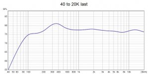
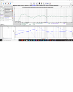
Still don`t get it completely, this is real mesaurement from 1 m at 1 speaker, and XSim simulation for exactly the same values used in xover which is measured.
Both smooting to 1/6
Also in XSIM it look`s like xover-point for woofer is 230hz ???....If it`s true it`s to high for woofer pointing down-projects.
Best regards John
Both smooting to 1/6
Also in XSIM it look`s like xover-point for woofer is 230hz ???....If it`s true it`s to high for woofer pointing down-projects.
Best regards John
Attachments
Last edited:
Hi I am munching on a sandwich and have a mini choc bar as an extra treat. Also using phone which can be an issue.Yes Ray it was, 🙂
Because eventually you can almost go"crazy" when you spend hour´s trying but nothing seem´s logical and strange things apere from time to time.
And i still have to close and restart XSim`s from time to time when it begains behave strange, and seems like XSim don`t like certain combinations.
Looks hard to get a "good" respone over about 88dB for the tweeter 🤔, and i don`t know if it`s for my "lost of skills" or if i have to shift phase on tweeter to get "maximum out of it"....Never done shifting phase simulations, and the xover-points in XSim lokks strange if i shift phase.
And the spl-curve seems somehow "stuck" at around 3500 hz no matter what I do?
I`m a little stuck here!
And don`t know when to be satisfied with the spl curve either
Best regards John
So right now I cannot see graphs etc. I feel the tweeter should work with 0.18- o.25mH coil with 5-10uF preceding the coil and 8-15uF on the opposite arm. Without any attenuation does that give you enough level.
I do know that a single fe500 starts falling off rapidly around 3 khz or so with a suitable second order for that frequency. With that a gentle third order on the tweeter can work maybe starting to fall off slowly at 5KHz. It may or may not work, it usually does when you can when you can play with levels via an Load, but it seems you may not have enough output from the tweeter left.
If you post your latest SIM I can look in about 6 hours time. Always worth swapping phase and trying to see if you can make a better solution, but values will have to change to accommodate the change.
I can now see your earlier graphs and I think they look reasonable.Hi I am munching on a sandwich and have a mini choc bar as an extra treat. Also using phone which can be an issue.
So right now I cannot see graphs etc. I feel the tweeter should work with 0.18- o.25mH coil with 5-10uF preceding the coil and 8-15uF on the opposite arm. Without any attenuation does that give you enough level.
I do know that a single fe500 starts falling off rapidly around 3 khz or so with a suitable second order for that frequency. With that a gentle third order on the tweeter can work maybe starting to fall off slowly at 5KHz. It may or may not work, it usually does when you can when you can play with levels via an Load, but it seems you may not have enough output from the tweeter left.
If you post your latest SIM I can look in about 6 hours time. Always worth swapping phase and trying to see if you can make a better solution, but values will have to change to accommodate the change.
The tweeter level doest look low to me.
The bass mid transition also looks reasonable in terms of the drivers and their output levels. If the dip bothers you and doesn't sound good. You can try altering the bass response which will take away some of the extreme LF which may help you with the dip.
Nice with a mini choc bar as desert...But the sandwich is not your lunch huh?......UK and Norway is real sandwich-guy`s 🙂
Had test with "0.18- o.25mH coil with 5-10uF preceding the coil and 8-15uF opposite arm", but have no succes "on the whole".
Have put some hours in XSim but can`t get it much better then earlier....a little frustrated, and maby my goal is sat to high.
Give you totally free hands to build up this xover Ray, even if it goes away from the original a lot (everywhere on the filter)
Best regards John
- Home
- Loudspeakers
- Multi-Way
- 3 way upgrading Jamo D590 replacements and filter question