what about my concept baffle then where it changes in size for each driver? its like a varying baffle step. it will effect tweeter mid and woofer differently because of the arch type shape (varying baffle step)
sound waves arnt square, ok some are, but.....
sound waves arnt square, ok some are, but.....
what about my concept baffle then where it changes in size for each driver? its like a varying baffle step. it will effect tweeter mid and woofer differently because of the arch type shape (varying baffle step)
sound waves arnt square, ok some are, but.....
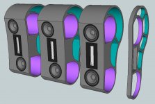
You can simulate any baffletype in the program I link to. Try it, its easy and very educating
Bit limited by only being able to use one driver shape at a time, but very educational all the same.
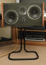
I was always under the impression that lining them up down the middle would be best, but that looks to almost be the worst thing to do...
I think the diagonal like the first photo would probably be easiest.
Edit:
Just had a play with the baffle shape WaVeInFoRm is playing with, and it can be simulated you just need to add more corners and drag it to shape.
Can't seem to find a way to curve the front face like I want to do in my design.
Last edited:
well got me 2 25mm 8x4 sheets to work with... cost a fair bit, and they weign 60kg each!
also i have found a broken sign made from some strange but very bendy material, so i can play with the 3d baffle idea i had. the idea being to provide some load to all drivers by changing the distance like a triangular semi waveguide that gets bigger as it goes down the speaker. also the angle from top to botton would change from steep curve at the top to shallow long curver at the bottom, to match frequency shapes. in theory. gunna be fun regardless
also i have found a broken sign made from some strange but very bendy material, so i can play with the 3d baffle idea i had. the idea being to provide some load to all drivers by changing the distance like a triangular semi waveguide that gets bigger as it goes down the speaker. also the angle from top to botton would change from steep curve at the top to shallow long curver at the bottom, to match frequency shapes. in theory. gunna be fun regardless
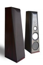
As you will find out, in later time, they are not "diagonal" (or should not be). The tweeter is in the middle... keeping with a vertical alignment as you can verify from the second good example. They are just offset, to the side, for a better baffle/driver relationship as you can find using "The Edge" or others softwares that modulate the front baffle. Because the woofers work much better out of symmetry positions or resonances/peaks at fixed frequencies. There's this classic speaker that was much praised here in diyAudio the Gales. You can find that mid and tweeter are trying to keep a vertical alignment.I was always under the impression that lining them up down the middle would be best, but that looks to almost be the worst thing to do...
I think the diagonal like the first photo would probably be easiest.
Attachments
Last edited:
Yes upon closer inspection I can see now that they are not diagonal.
Playing with SketckUp to get an idea of what it might look like if it was offset... I don't think it upsets the balance of the design at all.
Also extended both sides by 25mm to see what it would look like wider.
Playing with SketckUp to get an idea of what it might look like if it was offset... I don't think it upsets the balance of the design at all.
Also extended both sides by 25mm to see what it would look like wider.
Attachments
my wood arrives tomorrow, and i am seriously contemplating sawing by hand, as it is 25mm i should beable to cut it square (i hope)
post seem to come in waves...
i am not entirely sure why the tweeter is so much louder than the rest of the speaker, i know part of it is to do with the rubbish crossover. is it to do with the ohm of the speaker? does a 3ohm draw more curent than a 6ohm? (for example)
i am not entirely sure why the tweeter is so much louder than the rest of the speaker, i know part of it is to do with the rubbish crossover. is it to do with the ohm of the speaker? does a 3ohm draw more curent than a 6ohm? (for example)
post seem to come in waves...
i am not entirely sure why the tweeter is so much louder than the rest of the speaker, i know part of it is to do with the rubbish crossover. is it to do with the ohm of the speaker? does a 3ohm draw more curent than a 6ohm? (for example)
Tweeters usually have higher sensitivity than other drivers.
Like DrDyna said, today's tweeters have high sensitivity, a combination of powerful magnets and light materials. In any given driver combo, chances are the tweeter will be the most sensitive driver, sometimes by far. The way to attenuate it is with an "L-pad", i.e. a series resistor and a parallel one. There are several online calculators for this. Very easy to do too.
Alternately to padding down the tweeter which may hurt sound, you can double the drivers for a 3db gain, or put them in parallel for a 6db gain (provided the amp will support parallel wiring of drivers).
This is what I plan to do to try bring my mids up to the same 95db level of the Raal tweeters.
This is what I plan to do to try bring my mids up to the same 95db level of the Raal tweeters.
Alternately to padding down the tweeter which may hurt sound.
Nah it won't hurt a bit. More likely to cause harm by using multiple mids as you have issues with driver spacing, potential for lobing problems etc..
i have been slowely collecting all the bits and bobs to make the cabinets, and have learnt a good deal about routers in the process.
the seem a infinatly valuble investment, i should be able to cover my speakers in a lovely wood finish...
now i have been looking at all routers i can find, and the only way i see to make the small diamiter holes would be to use the guide on the router to make a bigger hole. then clamp that over the baffle, and run the router inside the larger hole, to make the smaller one. getting it the right size will require some planning, put i cannot find any detailed tutorials.
standard plung routers seem abit to big and bulky, i was looking at this lovely little makita Makita RT0700C Router / Laminate Trimmer with Trimmer Base 240V (RT-0700-C)
its a quality tool and has hole in the guide plate i can use to make a router compass. and it should be suited for vanearing. just wondering what opinions be on this
the router base seems almost too small to be logical, anyone know more on this subject? all i need is to cut accurate holes in 25mm mdf and flush mount drivers. and also trim ply/vaneer
also.. they sell a kit with all the other base plates. Makita RT0700C router trimmer - YouTube
i have been slowely collecting all the bits and bobs to make the cabinets, and have learnt a good deal about routers in the process.
the seem a infinatly valuble investment, i should be able to cover my speakers in a lovely wood finish...
now i have been looking at all routers i can find, and the only way i see to make the small diamiter holes would be to use the guide on the router to make a bigger hole. then clamp that over the baffle, and run the router inside the larger hole, to make the smaller one. getting it the right size will require some planning, put i cannot find any detailed tutorials.
standard plung routers seem abit to big and bulky, i was looking at this lovely little makita Makita RT0700C Router / Laminate Trimmer with Trimmer Base 240V (RT-0700-C)
its a quality tool and has hole in the guide plate i can use to make a router compass. and it should be suited for vanearing. just wondering what opinions be on this
the router base seems almost too small to be logical, anyone know more on this subject? all i need is to cut accurate holes in 25mm mdf and flush mount drivers. and also trim ply/vaneer
also.. they sell a kit with all the other base plates. Makita RT0700C router trimmer - YouTube
I've had my eye on this for a while, but I'd have to get a new router, I don't think it'd fit on my little one.
M.Power CRB7 Router Jig: Madisound Speaker Store
Edit: I've got one of these for my router now that I use every time, it works great.
http://www.madisoundspeakerstore.co...-200-perfect-circle-guide-for-plunge-routers/
Edit2: Also, I don't think that router you linked is a plunge router, you might have better luck with something like this:
http://www.toolstop.co.uk/bosch-pof-1400-ace-1400w-diy-router-240v-p7049
Last edited:
Here is a small video of you guys of my progress so far. enjoy!
There will be more.
3 way - Tower Project with Sea's Drivers - Construction - Part 2 - YouTube
There will be more.
3 way - Tower Project with Sea's Drivers - Construction - Part 2 - YouTube
I thought it was about time i showed my progress, turns out my camcorder takes useless stills, but you can still just about make out the speakers....😉
here are the uncut bass ports
I have made a few minor modifacations to my origional design.
The cabinets will be lined with fiberglass..
The bass cabinet will have one large shelf brace (with a huge hole in) so that no panels in the speaker are large enougth to vibrate
All walls will be 32mm thick, with the addition of some lovely looking 6mm plywood on all faces...
The Ply shall be sanded and waxed
And the port will now be made from drainpipe wrapped in foam with exastic bands
The xover will be mounted on a removable board behind the driver
The top section infront of the xover will have some lose dampening to absorb midrange resonances...
The rest of the cabinet will be left clear, so there is no obstruction around the driver or port
I will upload a proper HD video when the cabinets are coated in ply and are looking nicer....🙂
An externally hosted image should be here but it was not working when we last tested it.
here are the uncut bass ports
An externally hosted image should be here but it was not working when we last tested it.
I have made a few minor modifacations to my origional design.
The cabinets will be lined with fiberglass..
The bass cabinet will have one large shelf brace (with a huge hole in) so that no panels in the speaker are large enougth to vibrate
All walls will be 32mm thick, with the addition of some lovely looking 6mm plywood on all faces...
The Ply shall be sanded and waxed
And the port will now be made from drainpipe wrapped in foam with exastic bands
The xover will be mounted on a removable board behind the driver
The top section infront of the xover will have some lose dampening to absorb midrange resonances...
The rest of the cabinet will be left clear, so there is no obstruction around the driver or port
I will upload a proper HD video when the cabinets are coated in ply and are looking nicer....🙂
Last edited:
Found some lovely plywood in the local B&Q... I sneekly took a tub of beeswax... and then appled it to a small section of one of the sheets.😱
Looks nice wet.... Tommorrow when i go back there and its dryed, I will now be able to get a idea of what the finish will look like..
Going to look lovely with this Ply, Still need to sort out the first draft XoVeR though...
I am using the PMS xover, with modified resister values that I will experiment with....
Problem is, on his website the list of components includes 4 capacitors that are not shown on his schemetic. So i dont realy know what to order atm.
I really would be gratefull if someone could shed some light on this for me. Here is the direct link to the xover diagram, with the un matching list of capacitors....😕
http://www.troelsgravesen.dk/PMS.htm#The%20final%20PMS%20version%205%20crossover
Xovers and simulations are not my strong point....
Still the cabinets are going to be look lovely...
Last edited:
Got my ply today!
The main cuts done have been made by a very rude un-obiding moron.... in the local B&Q
I was hoping to get them all done, but he had such a rushfull uncaring attitude that I thought it best to finish the cuts at home.
Still I am happy with this PLY. Nothing beats real wood, much nicer than MDF
This evening I have been making out the bits that are going to cover the faces of the speaker boxes, ensuring that each bit lines up nicely.
I couldnt figure out which direction the grain of the wood was going. After studying the knots in the board... and comparing to a cut from a log.. I was finally able to assatain the flow of the wood, so as to ensure up, on the front of the speaker is the way the tree would be growing. I am sure the visual distance is marginal, however I was interested in learning 🙂
Anyway I thought i would show a picture of my nice PLY, despite the crappy camera...
It certainly has character
Just got to solve the formentioned X-Over problem.....😉
The main cuts done have been made by a very rude un-obiding moron.... in the local B&Q
I was hoping to get them all done, but he had such a rushfull uncaring attitude that I thought it best to finish the cuts at home.
Still I am happy with this PLY. Nothing beats real wood, much nicer than MDF
This evening I have been making out the bits that are going to cover the faces of the speaker boxes, ensuring that each bit lines up nicely.
I couldnt figure out which direction the grain of the wood was going. After studying the knots in the board... and comparing to a cut from a log.. I was finally able to assatain the flow of the wood, so as to ensure up, on the front of the speaker is the way the tree would be growing. I am sure the visual distance is marginal, however I was interested in learning 🙂
Anyway I thought i would show a picture of my nice PLY, despite the crappy camera...
It certainly has character
An externally hosted image should be here but it was not working when we last tested it.
An externally hosted image should be here but it was not working when we last tested it.
Just got to solve the formentioned X-Over problem.....😉
Last edited:
- Status
- Not open for further replies.
- Home
- Loudspeakers
- Multi-Way
- 3-way - Tower Speaker Project with Seas Drivers