I think the parameters for the CA26RFX need to be reviewed, then proceed to box design.
Are the manufacturer parameters the ones to use? Does anyone have recently measured results?
I've used the manufacturer's parameters for a BR and is within 6% of Madisound's recommended enclosure. I assume Madisound's are based on measured data as they have all the facilities available so SEAS data should not be too far off the mark.
Ted
My design is going to be 1st order electrical and will give my reasons when I post the design in a couple of weeks. Most of the number crunching is done and drawings started.
This will be basically the poverty version and probably will never be built by any one but I'm going to post it mostly to explain the choices I've made to give some insight into the process. It's also going to be there to get the ball rolling so others can pick it up and run with it to achieve higher heights with more advanced designs..... it needs to start somewhere.
Well first order is always where my thinking starts, mainly because of poverty, but experience with using book calculations tells me to start with 2nd : 3rd<->2nd : 3rd, as it works reasonably well at the expense of lots of components.
As you say; when working with good drivers XOs are easier,
As you say; when working with good drivers XOs are easier,
working with good drivers XOs are easier,
Some good drivers require complex XOs is it just that these drivers all have pretty smooth roll offs hence making an XO is a bit easier.
diyA 3-way Version 1
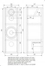
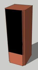
Here's Version 1 of the 3-way speaker where the goal is a simple economical build, hence the use of a single BR woofer. It can be adapted to a dual woofer sealed with some dimension changes and for every increase or decrease in height of 10mm, the volume changes by 0.904 litres in the bass chamber.
The Box
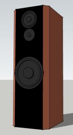
It's all made from 25mm MDF (or equivalent) so only one thickness sheet is required. The 45° vertical edges are there for a few reasons. It's done to reduce the baffle width around the mid driver, to allow easy construction using pre veneered MDF so no MDF edges are exposed, to help with edge diffraction and for aesthetics to take away a slab look. The woofer edge is exposed by about 5mm each side which adds to the aesthetics. These 45° panels can be added as drawn using 22.5° cuts or use of machined timber and can also be quarter round if desired. There are several other ways they can be formed such as machining after. It can be built without the 45° panels to give a more slab look.
The Mid Enclosure
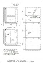
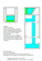
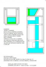
In the end I went to a simple oversized sealed enclosure (5 litres) as it allows a smoother roll off to the woofer which helps with crossover design. The acoustic roll off starts off around 400Hz and by 100Hz it's already 6dB down so will allow use of a lower order high pass crossover. It's oversized to allow better control of the back wave which is aided by the use of the angled back panel which ensures several reflections of the back wave before returning to the driver. Each reflection will reduce the energy in the back wave. The enclosure also allows the use of a TL type of enclosure for the mid and the angled panel is removed and a 190mm x 151mm hole cut in the back of the box. It's best to stuff the line 100% to reduce the pipe resonance and remove to suit taste. It can also be used as a pseudo OB mid by cutting the sides and back away in this area or leave the line open (such as the Infinity Renaissance 90) and only add some damping directly behind the driver to add some acoustic loading.
Inverted Mid & Tweeter
From the start this design was done with a 1st order crossover in mind. For 1st order (+ve polarity) we get a 15° downward tilt and by reversing the drivers we get an upward tilt which cancels the downward tilt (ref ZDP). In theory the driver spacing and horizontal offest should be positioned to give a 15° upward tilt but since I don't have the drivers I do not know the dimensions to the motor front plate but as drawn it would not be too far out. This also works for 3rd order (-ve polarity) which is used on the suggested crossover in posts #297, #311. What I like about the mid on top is it allows more flexibility in mid chambers, reduces baffle area around the mid and allows for an uninterrupted woofer chamber. This also allows use of a split enclosure if desired. For even order crossovers the drivers can be changed back to tweeter on top and the mid enclosure dropped down to suit. It would require a path from the lower chamber to the upper tweeter chamber as this is required for the woofer box volume. Doing this however removes the possibility of the TL or OB mid.
The Woofer Enclosure
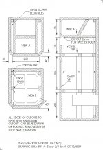
A no brainer and is 66 litres with Fb=33Hz. The design is derived via an old version of LspCAD and other software will give different outcomes. It's close to Madisound's recommended BR size for the CA26RFX so wouldn't be too far off the mark. I've used the manufacturer's T/S parameters and even though they would vary from measured, the important ratios Fs/Qts and VasFs² would not vary greatly. Simple shelf bracing is used and the cleat (ref "X" in the drawing) goes all the way around to help with closure of the back panel. The port is 104mm inside diameter PVC pipe and size chosen to keep the vent velocity low. I wouldn't go smaller than 86mm inside diameter PVC pipe. Any changes in diameter alter the length and there are formulae available to calculate this is more simple is to do a 66 BR in WinISD or equivalent and add a 104 x 254 port. Note the tuning frequency (Fb) and change to port diameter as desired. The new length will be calculated for the new diameter for the same Fb.
Damping
I've used a scheme that's been successful in my BR projects and is recommended by a lot of BR designers. The main damping hangs down like a curtain mid box and has an air gap to the back panel. The mid enclosure is lined to help with back wave reflections and provide some absorption. The remainder is filled up to the driver motor and an air gap up to the back of the cone.
Rebates and Chamfer
All drivers are rebated so they are flush with the baffle and the sizes on the drawing are nominal only so should be checked against the actual drivers. This helps with edge diffraction and reasons are well documented. It's more applicable to tweeters than mids and woofers but it's always a good idea to do it on the mid as well. The baffle opening into the box for the mid and woofer have a 45° chamfer to allow better airflow from the mid and woofer. It's an important part of this design and larger chamfers than shown on the drawing can be used but make sure there is enough material remaining for driver mounting screws / fasteners.
Even though this may never be built, it gives some insight into my thinking and why choices were made in this design. Some of this can be transferred to other designs and is a bit of a teaching tool for those that want to design a 3-way. In addition it kicks off a design in this thread.
Here's Version 1 of the 3-way speaker where the goal is a simple economical build, hence the use of a single BR woofer. It can be adapted to a dual woofer sealed with some dimension changes and for every increase or decrease in height of 10mm, the volume changes by 0.904 litres in the bass chamber.
The Box
It's all made from 25mm MDF (or equivalent) so only one thickness sheet is required. The 45° vertical edges are there for a few reasons. It's done to reduce the baffle width around the mid driver, to allow easy construction using pre veneered MDF so no MDF edges are exposed, to help with edge diffraction and for aesthetics to take away a slab look. The woofer edge is exposed by about 5mm each side which adds to the aesthetics. These 45° panels can be added as drawn using 22.5° cuts or use of machined timber and can also be quarter round if desired. There are several other ways they can be formed such as machining after. It can be built without the 45° panels to give a more slab look.
The Mid Enclosure
In the end I went to a simple oversized sealed enclosure (5 litres) as it allows a smoother roll off to the woofer which helps with crossover design. The acoustic roll off starts off around 400Hz and by 100Hz it's already 6dB down so will allow use of a lower order high pass crossover. It's oversized to allow better control of the back wave which is aided by the use of the angled back panel which ensures several reflections of the back wave before returning to the driver. Each reflection will reduce the energy in the back wave. The enclosure also allows the use of a TL type of enclosure for the mid and the angled panel is removed and a 190mm x 151mm hole cut in the back of the box. It's best to stuff the line 100% to reduce the pipe resonance and remove to suit taste. It can also be used as a pseudo OB mid by cutting the sides and back away in this area or leave the line open (such as the Infinity Renaissance 90) and only add some damping directly behind the driver to add some acoustic loading.
Inverted Mid & Tweeter
From the start this design was done with a 1st order crossover in mind. For 1st order (+ve polarity) we get a 15° downward tilt and by reversing the drivers we get an upward tilt which cancels the downward tilt (ref ZDP). In theory the driver spacing and horizontal offest should be positioned to give a 15° upward tilt but since I don't have the drivers I do not know the dimensions to the motor front plate but as drawn it would not be too far out. This also works for 3rd order (-ve polarity) which is used on the suggested crossover in posts #297, #311. What I like about the mid on top is it allows more flexibility in mid chambers, reduces baffle area around the mid and allows for an uninterrupted woofer chamber. This also allows use of a split enclosure if desired. For even order crossovers the drivers can be changed back to tweeter on top and the mid enclosure dropped down to suit. It would require a path from the lower chamber to the upper tweeter chamber as this is required for the woofer box volume. Doing this however removes the possibility of the TL or OB mid.
The Woofer Enclosure
A no brainer and is 66 litres with Fb=33Hz. The design is derived via an old version of LspCAD and other software will give different outcomes. It's close to Madisound's recommended BR size for the CA26RFX so wouldn't be too far off the mark. I've used the manufacturer's T/S parameters and even though they would vary from measured, the important ratios Fs/Qts and VasFs² would not vary greatly. Simple shelf bracing is used and the cleat (ref "X" in the drawing) goes all the way around to help with closure of the back panel. The port is 104mm inside diameter PVC pipe and size chosen to keep the vent velocity low. I wouldn't go smaller than 86mm inside diameter PVC pipe. Any changes in diameter alter the length and there are formulae available to calculate this is more simple is to do a 66 BR in WinISD or equivalent and add a 104 x 254 port. Note the tuning frequency (Fb) and change to port diameter as desired. The new length will be calculated for the new diameter for the same Fb.
Damping
I've used a scheme that's been successful in my BR projects and is recommended by a lot of BR designers. The main damping hangs down like a curtain mid box and has an air gap to the back panel. The mid enclosure is lined to help with back wave reflections and provide some absorption. The remainder is filled up to the driver motor and an air gap up to the back of the cone.
Rebates and Chamfer
All drivers are rebated so they are flush with the baffle and the sizes on the drawing are nominal only so should be checked against the actual drivers. This helps with edge diffraction and reasons are well documented. It's more applicable to tweeters than mids and woofers but it's always a good idea to do it on the mid as well. The baffle opening into the box for the mid and woofer have a 45° chamfer to allow better airflow from the mid and woofer. It's an important part of this design and larger chamfers than shown on the drawing can be used but make sure there is enough material remaining for driver mounting screws / fasteners.
Even though this may never be built, it gives some insight into my thinking and why choices were made in this design. Some of this can be transferred to other designs and is a bit of a teaching tool for those that want to design a 3-way. In addition it kicks off a design in this thread.
Attachments
Last edited:

diyA 3-way Version 1 crossover thoughts
I'm not going to post a crossover as since I'm not building this speaker I could never come up with final component values even though I've modelled a couple. Someone around here once said to use the lowest order crossover that gets the job done and more than half of that battle is won by this driver choice.
These drivers are very well behaved and scream out for a 1st order electrical crossover. I've built enough 1st order series (2-ways) and heard enough of Andy G's 1st order 3-ways to know that these drivers would do the job with ease. I'm sure Andy would agree with me on this.
Most builders are more comfortable with higher orders and there is a suggested crossover already been posted based on Troel's 3W. I've done some modelling and would be a good starting point. Joe has also kindly posted a crossover using the MCA15RCY. For a higher order crossover the 27TFFC would also be a good choice and maybe be better than the 27TDFC.
Post #297
http://www.diyaudio.com/forums/mult...o-3-way-reference-project-15.html#post1975922
Post #311
http://www.diyaudio.com/forums/mult...o-3-way-reference-project-16.html#post1976958
Post #314
http://www.diyaudio.com/forums/mult...o-3-way-reference-project-16.html#post1977829
Post #315
http://www.diyaudio.com/forums/mult...o-3-way-reference-project-16.html#post1977832
Hopefully someone with the expertise and equipment will step up to the plate and design a crossover for this.
Last edited:
Wow rabbitz you have been busy! I'll have to digest all that 😉 Nice drawings what are you using?
Definitely a good way to get the discussion moving!
Tony.
Definitely a good way to get the discussion moving!
Tony.
An old copy of AutoSketch R6 from Autodesk. Runs fine under Win 7 and see no need to upgrade as it's a treat to use and not bloatware like a lot of the newer stuff. It does not export well for images as you have to save in the old WMF and then open and save in a graphics application to save as JPG or PNG. With that you lose scaling abilities and some detail.
Last edited:
Here's Version 1 of the 3-way speaker
Inverted Mid & Tweeter
From the start this design was done with a 1st order crossover in mind.
The Woofer Enclosure
A no brainer and is 66 litres with Fb=33Hz.
Even though this may never be built, it gives some insight into my thinking and why choices were made in this design. Some of this can be transferred to other designs and is a bit of a teaching tool for those that want to design a 3-way. In addition it kicks off a design in this thread.
your design look a lot like this.
Cyclop-Laurent,
I had visions of a Maestro Utopia lookalike.
http://focal.tchernovaudio.com/goods/pdf/maestro ref.file GB pdf.pdf
http://www.digitalear.com/assets/images/gallery/focal/pdfs/maestro-utopia-8-10.pdf
Last edited:
They're a bit more up market than my proposal which could be built for less than the price of 1 tweeter on the others. 😱
I've always liked the Utopia and there's no reason this design couldn't be made to look like that.... sound like that is a different matter. 😉
I've always liked the Utopia and there's no reason this design couldn't be made to look like that.... sound like that is a different matter. 😉
Thanks Rabbitz, I'd like some sort of cad program... I started to play with sketchup, but it's not really the same 😉
Couple of thoughts since you posted last night.... one was with regards to the woofer placement, probably not necessary as the dimensions are within the guidelines (ie shouldn't exhibit pipe tendencies) but it can't hurt either, and that is to position the woofer at the 1/5th distance from the top (of it's chamber) rather that in the centre... will get it a little closer to the mid as well 🙂
The other was about the vent size, another option is to use two vents of a smaller diameter... in unibox 66L and 33fb with 104 diameter port It shows me a port resonance of 497Hz whereas with two 63mm diameter ports the port resonance is a bit higher at 673 Hz and almost shows no effect on the response graph. Port length is a bit shorter as well... (I don't have the box dimensions handy so can't say if that is advantageous or not 🙂 ) when modeling I like to try and get the port resonance as far outside of the range that the driver should be reproducing as possible...
That's a bit smaller overall port area but still enough to avoid chuffing... just a thought 🙂
Tony.
I usually like the woofer much lower than it is but it's carrying a lot of the mids as it would be crossed over higher due to the use of the MCA15RCY. All mine have been crossed over below 150Hz (due to using 6.5" mid woofers) which means the woofer was mostly doing the doof doof and little squawk squawk.
The woofer's location was based on a study where the low frequency driver is located at the centre or below the centre will minimise standing waves across the height and width.
The port resonance I get from 2 programs is 677Hz for 104 x 254.
Good thinking Tony and all tips and ideas are good as it takes as starting point and moves it onward and forward. I sit back and watch now.
Thanks Rabbitz, I'll have to check the unibox again... interestingly it gave me a port length of around 27cm for 33 Hz Tuning with 66L enclosure, I might need to check that I put in all of the T/S params correctly!
The 1/5th distance was a recommendation in David Weems' book for suppressing the 5th harmonic (more aimed at pipe resonances). Have you got a link to that study, I'd be interested to read it 🙂 As It is something I will need to consider myself at some point in the future when I redo my woofer cabinets...
Had we decided on a rough crossover point yet? Even with 5" drivers it should be possible to go down as low as 200Hz fairly comfortably (I haven't modeled the MCA15RCY yet so I could be wrong)!
If we only use a 1st order on the woofer then I guess proximity to the mids will be more of a consideration too (and possibly time alignment as well) as it would only be down 12db (electrically) at 800 Hz with a 200Hz crossover point...
Tony.
Nice work Rabbitz.
I've been looking at using two CA26RFX woofers in a 110L sealed box with filters that start relatively low to bring sensitivity down to about 94dB for BSC. I've also simulated the two woofers in a BR box which also look very promising. With this and the MCA15RCY, the 27TFFC tweeter seems to match better. Thanks for that suggestion whoever made it. 😉
I'm looking at 2nd order filters, will post the values when I'm happy with the simulation.
Thanks Rabbitz, I'll have to check the unibox again... interestingly it gave me a port length of around 27cm for 33 Hz Tuning with 66L enclosure, I might need to check that I put in all of the T/S params correctly!
The 1/5th distance was a recommendation in David Weems' book for suppressing the 5th harmonic (more aimed at pipe resonances). Have you got a link to that study, I'd be interested to read it 🙂 As It is something I will need to consider myself at some point in the future when I redo my woofer cabinets...
Had we decided on a rough crossover point yet? Even with 5" drivers it should be possible to go down as low as 200Hz fairly comfortably (I haven't modeled the MCA15RCY yet so I could be wrong)!
If we only use a 1st order on the woofer then I guess proximity to the mids will be more of a consideration too (and possibly time alignment as well) as it would only be down 12db (electrically) at 800 Hz with a 200Hz crossover point...
Tony.
Tony
I'll bet my left one that your T/S parameters have been entered correctly. Each program tends to come up with different results and I only use my old LspCAD as I've been using it for ages and get consistent results. My sizes were based on QL=15 and 30% fill.
I've done a calculation by hand on the CA26RFX using QB3 alignment tables and formulae and end up with:
Vb=63.17 litres (QL=15), 65.49 litres (QL=7) (for ref BB4 gave 63.3 litres)
Fb=32.89Hz (QL=15), 33.94Hz (QL=7)
F3=36.84Hz (QL=15), 38.45Hz (QL=7)
Using the standard formula, the calculator gave me a port 104 x 265 long.
The study was JAES April 1984 (Shinichi Sakai) and is referred to the Loudspeaker Design Cookbook. Actually my mains woofer setup is closer to your suggested 1/5 distance. Is that to the cone centre line or edge?
I was thinking of a crossover point (2nd order) around the baffle step frequency of around 340Hz so 300Hz to 400Hz could work well but would maybe need to be higher for 1st order. The MCA15RCY in my mid enclosure would be dropping too much to crossover below 300Hz. You could crossover lower with a vented mid enclosure.
The tweeter should slot in between 2.5kHz to 3kHz.
With 1st order the amount of mids from the woofer can be a problem. One solution it to have it low so it's truely off axis for higher mids. A good partner with 1st order is an oversized zobel (say 15uF + 8R2) as it helps it to drop dB where it's not required. But I've heard a lot of Andy's using 1st order on the woofer and mids were never a problem.
Last edited:
Nice work Rabbitz.
I've been looking at using two CA26RFX woofers in a 110L sealed box with filters that start relatively low to bring sensitivity down to about 94dB for BSC. I've also simulated the two woofers in a BR box which also look very promising. With this and the MCA15RCY, the 27TFFC tweeter seems to match better. Thanks for that suggestion whoever made it. 😉
I'm looking at 2nd order filters, will post the values when I'm happy with the simulation.
Andre
That would be great if you can post the crossover values as more contributors we have in this thread, the better the outcome.
I personally prefer the 27TFFC over the 27TDFC as it seems to have a bit more air and sparkle to the sound but prefer to use the 27TDFC in 1st order due to the lower Fs. I think Troels made some comments where he found the 27TFFC was more to his liking or may have suited that particular design better.... can't remember which. The use of it here is based on Troels work on the 3W and PMS.
Your right rabbitz, I hadn't put in any incorrect parameters. I know I got quite different results between winisd and unibox in the past, and I've used unibox as my main modelling program for a long time now 🙂
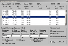
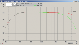
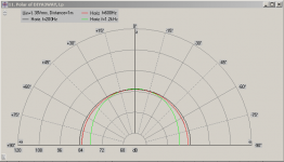
I was playing with akabak tonight with the CA26RFX, one of the nice things with it is it suggests alignments with all different parameters of each. I found this one interesting:
Box volume 73L tuning freq 29.8 Hz... the thing I liked most about it was it had good extension, but also quite good transient response. F3 is about 33Hz and F10 is about 23Hz (when modelled in unibox, slightly higher in akabak). It has a slightly softer rollof than your usual vented box but I thought it was an interesting alternative.
One of the things I really like about akabak is the range of things you can simulate, and the depth of what you can add in as well, for instance driver geometry cabinet dimentions, room reflections etc can all be put into the model (not that I've done any of that yet!)
edit last graph is the unibox version of the same alignment.
Tony.
Attachments
Last edited:
- Home
- Loudspeakers
- Multi-Way
- 3-way reference project??