Hi all
some years ago I built a couple of 2 way speakers based on mid-woofer SB17NRXC35-8 and a tweeter SB26STC-C000-4.
The cabinet was sealed with a volume of 15L
I enjoyed a lot them, but I feel that bass are too poor. So I decided to realize a new project 3 way that is an extension of that one.
I'm evaluating 2 sub-woofer: SB26SFCL38-8 or dayton sd270a-88 (the first one to be preferred bcause it is 8 ohm).
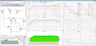
I designed the cabninet, all SPL response and the crossover. My only problem is that the final impedence seems too low (about 2 ohm expecially at high freq) and I'm not able to adjust it. I tried with LPAD, but I'm not so familiar and I was not able to reach good result.
Can someone help me?
some years ago I built a couple of 2 way speakers based on mid-woofer SB17NRXC35-8 and a tweeter SB26STC-C000-4.
The cabinet was sealed with a volume of 15L
I enjoyed a lot them, but I feel that bass are too poor. So I decided to realize a new project 3 way that is an extension of that one.
I'm evaluating 2 sub-woofer: SB26SFCL38-8 or dayton sd270a-88 (the first one to be preferred bcause it is 8 ohm).
I designed the cabninet, all SPL response and the crossover. My only problem is that the final impedence seems too low (about 2 ohm expecially at high freq) and I'm not able to adjust it. I tried with LPAD, but I'm not so familiar and I was not able to reach good result.
Can someone help me?
Attachments
Hi!
25uF with 150uH for tweeter seams strange. I think capacitance is too high. Try smaller cap and higher value inductor.
Disconnect this 25uF and see if the impedance normalizes just to confirm.
You can use this online tool to help you find initial values:
https://www.diyaudioandvideo.com/Calculator/ApcSpeakerCrossover/

Ron68 beat me to it, with his question about the tweeter cap.
I would guesstimate 4.7 - 8.0uF with 180-250uH for a SB tweeter. if you wanted third order Xover same values with the additional cap at approx 8-20uF.
If you open circuit the tweeter cap you can see what the overall impedance looks like, and verify that with the tweeter leg out of circuit it goes back to a more sensible level. If that is not the case, it would seem you need some further work on the other components.
I think it should be an easy fix, and maybe with more sensible cap values you may have the possibility of a re instating the LPad if its needed.
Determine where the problem comes from. Remove the tweeter section, and see what it looks like.
I add a 999 ohm resistor in front of each x-over temporarily. It's often the mid filter causing the problem.
The 150uf on the woofer probably isn't the issue, but can you use something like 80uf, and get the same results?
I add a 999 ohm resistor in front of each x-over temporarily. It's often the mid filter causing the problem.
The 150uf on the woofer probably isn't the issue, but can you use something like 80uf, and get the same results?
Also 150 uF for bass shunt seems to high. This leads to a 4 ohm impedance using an 8 ohm driver.
You also need to address baffle step unless the speakers are on- or in-wall. This will reduce total senstitivity quite a bit and you will have to use L-pads.
Did you try using the crossover optimizer, also including an L-pad?
You also need to address baffle step unless the speakers are on- or in-wall. This will reduce total senstitivity quite a bit and you will have to use L-pads.
Did you try using the crossover optimizer, also including an L-pad?
Thanks both for the support.
You are right, that cap is the cause of the low impedence. But change it is not so easy.
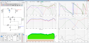
Attached 2 simulation with 2^ order and 3^ order filter.
In both cases I still have a zone with low impedence, but I loose also the coupling with the midrange 🙁
You are right, that cap is the cause of the low impedence. But change it is not so easy.
Attached 2 simulation with 2^ order and 3^ order filter.
In both cases I still have a zone with low impedence, but I loose also the coupling with the midrange 🙁
Attachments
All responses and impedences are simulated with VituixCADAre the measurements in box, simmed, or factory frds?
Did you sim BSC? Baffle step loss? It doesn't look like it. Pad the mid,and tweeter 4dB, and see how the impedance changes.All responses and impedences are simulated with VituixCAD
Last edited:
Yes. I imported the SPL and impedence graph from the datasheet. Then I simulated all drivers into the box (woofer with bass reflex 70L f=32Hz, mid and tweeter in closed box 10 L). Finally I calculated the diffraction and merged all response.Did you sim BSC? Baffle step loss?

I think that you may have to loose a bit more on the midrange, not a lot, but a bit more. Also you can probably lessen the wattage requirement for the resistor by moving it to the the other side of the cap, or somewhere else in the mid. Moving the resistor will obviously have knock on effect that will need some further adjustment to the mid Xover.
The break up region of the midwoofer could be lowered by the combination of a resistor and small c in parallel with the mid inductor, or by increasing the Xover slope to push these further down. If that isn't successful then a dedicated notch maybe needed. How did you deal with it in your earlier design?
I think there is more capability in the tweeter to go lower, so that should help if your do have to cut the mid output more steeply to suppress the break up.
It is worth noting that the diffraction tool in VituixCad can be used to generate and export 0-180 degree horizontal and vertical data for the drivers, which would give you some further insight into the power response and directivity.
I've always found 3-way systems a bit difficult. I'm also surprised you don't have any resistive pads or anything to control levels. It's hard to get the responses and levels both right with just the reactances.
You also gave to apply baffle diffraction to the simulated bass reflex response.with the reflex boost I guess
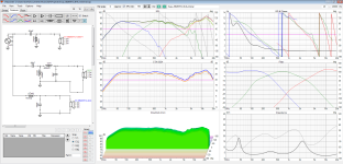
I would try adding a cap and resistor in series across the woofer terminals. Typically, I would start at 8uf and 8 ohms, but you can try maybe 40uf and 8 ohms. See if anything good happens. You want to make a sharper knee in the woofer response at 300hz I think. Another way to do that is to use a 3rd order filter. Maybe add a 3mH to that you have so far. Play with the values.After some tentative (copying from other projects) I found the solution attached even if I have to say that I'm not yet satisfied due to the 2 areas I highlthed. At least now the impedence is never below 4 ohm.
What do you think?
You want the woofer roll-off to be a mirror image of the mid roll-off around the 300hz line. See how currently one is steeper?
I'd add a notch on the mid at 5k too. Use about a ,7mH coil, and whatever cap size puts it at 5k for a starting point. Try to make the mid roll-off on the top end nice and smooth like the roll-off on the low end.
Last edited:
You did not load any diffraction responses. Besides that woofer works better in a sealed box: 70L full stuffed on a baffle 38x65cm.with the reflex boost I guess
You should get something like in the image below
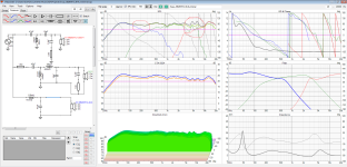
great question! this is the schema I used at that time.The break up region of the midwoofer could be lowered by the combination of a resistor and small c in parallel with the mid inductor, or by increasing the Xover slope to push these further down. If that isn't successful then a dedicated notch maybe needed. How did you deal with it in your earlier design?
Please note that I had no simulation with Vituix, but I used frd and zma found on internet.
I tried to simulate that schema with frd I'm using now and this is the result.
Both frd introduce difference into the simulation, but the main one is the tweeter.
- Home
- Loudspeakers
- Multi-Way
- 3 way project - final impedence too low