Generally you want to have a driver with a higher Qts for more driver control in open baffle applications. Also have tried testing the speakers moved even further away from the wall? Moving them further away from the wall will help solve cancellation issues you might have in frequencies cancelling each other out, thus better bass response and such if your sound sounds thin.
The idea of a dipole is to interact with the room less than a monopole.The OB interacts with the room so much that outdoor measurements are, IMHO, close to useless.
If you care to rotate the images, viewers like myself would appreciate more of the work(time and effort) you put in. if you spend 5sec to rotate each image before uploading them otherwise we(each one of us) will have to download all the images then rotate them ourselves and that will take us more time.
I don't think that's the issue. Some times the attached pictures are rotated no matter the orientation from the source. It happens on my phone but never from PC. The source is always onedrive.
Sorry attachment forgotten
May I refer you to a statement of fact, which at one time you fund enlightening:
"Design goal: 80Hz - 400Hz in a sealed alignment.
A speaker + box_alignment that naturally meets the 80Hz - 400Hz design goal and uses equalization mainly for room effects will normally have better sound than a speaker+box which needs extensive equalization just to be flat over the main BW."
Hey Scott.
Indeed, that helped me at the time.
You state that as a matter of fact, but it is just one opinion. An informed opinion, but not a universal truth. I have come across others with informed opinions who were using boxes and moved onto OB, so I'm curious to understand how it sounds and if I prefer that to sealed.
And finally, to be brutally honest here (but in hopes of ultimately helping you) judging by the pictures of your room, it must be horrible sounding. Thus, it's not your speakers per say, it's that awful room.
Maybe I should move homes because of the listening room? You might have missed the first post where I recognized the room is nasty and room treatment was under way? I've known this for a while and tried some DIY approaches but didn't look good and since it's the living room I contracted the work.
BTW, it's "per se".
I have a 3 way plus sub OB system (a single 12" woofer with a 12" pro-sound coaxial for mid+tweet). So somewhat similar to what you are looking to build. My experience is that a single 12" woofer is sufficient if you cross over to the sub around 60Hz. My woofer is in a 14" wide by 8" deep "U baffle" and has 8mm of Xmax. I sometimes play it loud enough that it disturbs my wife upstairs and I do not hear any distress from the woofer. SO I hope that answers your original question.
Thanks for sharing this! May I ask which driver you use for the bottom end? And what kind of music do you listen to and how loud? More on the acoustic side of instruments, rock, classical?
It's good to know one 12" works for you from 60Hz. Maybe one 10" allows me to get a feeling if OB is for me before buying more drivers. Crossing over to my subs at 60Hz would be good, and the 10" should be ok to go up to 300Hz to hand over to the 8".
Scott may be right about your room. The hard floor, in particular, strikes me as bad. A carpet would help as would some wall and ceiling treatment.
Indeed. FWIW, I usually have a 2" wool rug covering most of the floor, but it's not enough. So the room treatment will cover the whole front and back walls and ceiling. What I cannot treat are the left and right walls. OB could be very good in having the nulls to the sides in this case.
The rest of this post is derived from my experience and I will note that others may have different experiences: As to where to measure from; that, IMHO, is the hardest part of OB design. If you measure very close it's not representative of what the system's power response is. The OB interacts with the room so much that outdoor measurements are, IMHO, close to useless. So after much messing around I have settled on measuring at the listening position (and the general vicinity adding some averaging). Compared to other speakers I've had in the room, unfiltered OB measurements look not so great, but sound very nice. So if you are obsessed with measurements maybe OB won't be for you as you'll never get rid of all of the wiggles in your curves (not without a lot of smoothing).
At what angle do you sit from your speakers? The usual equilateral triangle, so 60 degree angles and you being at 30 degrees from your speakers?
I ask because I'm set up in an equilateral triangle, and Juhazi's paper recommends the listening angle should not exceed 15 degrees for OB, which would be impractical in my case.
Thanks for the input!
The idea of a dipole is to interact with the room less than a monopole.
Where in the room should I measure? 2m away on speaker horizontal axis? At what height? Or at the listening position?
A good link by puppet!
More info about how a monopole vs. dipole interact with walls differently
Finke Dipolplus - Alles über offene Schallwände
Kreskowsky roomgain and Boundary effects
Linkwitz Room Acoustics
Saunisto (VituixCAD man) Cardioid bass
More info about how a monopole vs. dipole interact with walls differently
Finke Dipolplus - Alles über offene Schallwände
Kreskowsky roomgain and Boundary effects
Linkwitz Room Acoustics
Saunisto (VituixCAD man) Cardioid bass
Last edited:
The Gainphile measurement plan has a major flaw: the "woofer" measurement. Here is why:
When you are trying to measure low frequencies you cannot measure in the far field because you will get interference from nearby boundaries and you want to exclude that from your measurement. Only a tricky distant (>2m away) measurement in a huge flat outdoor space would be free of this down to 10Hz or 20Hz. So instead Gainphile chose to do a nearfield measurement. A nearfield measurement rejects much (not always all) of the "room reflections" that cannot be gated away because the mic is placed so close to the source and the reflected sounds are relatively small in amplitude, and so practically disappear from the measurement (they are still there, just at very small amplitude).
Then Gainphile says to "make a 1m measurement at the midrange axis" and says the reverse the phase, etc. I assume this is to get the woofer-to-mid crossover polarity correct, etc.
Now this kind of approach would be perfect for a closed box, but it's missing the very important contribution from the rear wave that happens for a dipole system. A 1m measurement, unless it is in the open outdoors like I mentioned above, is essentially the far field, and so it will also capture any reflections from walls, floor, ground, etc. that are nearby if you use a long enough time series to be able to capture data down to 20Hz. This data will be corrupted by reflections and there will be peaks and dips in the response that do not accurately portray the output from the woofer section.
Without including the rear output (which a single front-opening nearfield doesn't) you will not be measuring the woofer sections' dipole response and you will not see the 6dB rolloff and the dipole peak. What good is that?
There is a better, albeit more complicated, way to obtain the dipole response that is great for low frequencies. I first heard of this from John Kreskovsky. For frequencies under 200Hz, a dipole can be approximated as two point sources separated by some distance and with one having reverse polarity. Because the wavelengths are large for these low frequencies, this is a very good approximation to the free-field response of a real-world dipole woofer or subwoofer system. You have to synthesize the free field response from two measurements and knowledge of the physical size of the system (the front to back pathlength) using some kind of crossover modeling software.
Here is what you do:
- Take a nearfield measurement of the response from the front
- Take a nearfield measurement of the response from the rear
- Find the front-to-back pathlength
- Import the two responses
- If using minphase data, invert the polarity of the rear measurement
- Add delay to the rear wave to mimic the extra distance it must travel to the listening position*
- Reduce the amplitude to account for the difference in distance traveled between the front and rear output and the listening position*
Where is the listening position? This determines the relative delay between front and rear output, as well as the relative distance, which in turn dictates the relative SPL of the two waves when they reach the listener.
Example:
The listening position is directly in front of the front of the dipole woofer, 2m away. The front-to-back pathlength of the system is 0.5m. At the listening position, the front output (at the front mouth) is 2m away but the back output is 2.5 m away. This results in a small SPL difference that will impact how the front and rear waves add, and becomes significant as the front to back pathlength increases. Calculate this SPL difference and reduce the SPL of the rear output by this much. The relative distance of the rear output to the listener compared to the front output is 0.5m. This gives rise to an additional phase rotation, because the wave has to travel farther to the listener. It's just a delay, so add the amount of delay corresponding to sound traveling 0.5m and add that to the rear output. Make sure the polarity of the rear output is opposite of front. If you use a minphase measurement, this is not captured by the data and so you must manually invert the polarity. If you use measured phase, the inverted polarity will already be included in the measurement data. Now add the front and rear outputs (these will be complex numbers), take the magnitude of the sum, and convert to SPL.
Voila! You have accurately modeled your dipole woofer (at one position in space at least)! The only thing to consider is that you have modeled the free-field (full space) output and you will be using the speaker in a room that is at least half-space and that increases the SPL level by 3dB compared to the full space level.
With that process completed and a bit more familiar, you can change the (listening) position to other locations, e.g. 2m away and 45 degrees off axis, and redo everything to get the SPL there as a function of frequency. Since the woofer section has a dipole response pattern, the SPL will be quite different as you move off axis. You can create an entire polar map of the output in this way if you wish. Unless you toe in the woofer section, you will be listening at some off-axis location and it is useful to know the response there.
This may sound very complicated, however, all of the additions and so on are simplified when you use a capable measurement-based crossover modeling tool, e.g. VituixCAD:
VituixCAD home page
I use my own ACD tools for these tasks, but can highly recommend VituixCAD.
Last edited:
Good catch Charlie! I was going to mention this but you beat me to it.
John K is brilliant, but I don't think his approach works for my situation. My OB bass is in a U baffle that is moderately stuffed with poly to make the rear ouput somewhat lossy. Plus the walls of the U baffle are not quite straight. I did this (tapered wall and stuffing) to damp the ~380Hz resonance inherent to the 9" deep U (I run the bass up to ~300Hz). It works quite well.
I tried John K's technique and did not get good model-to-physical agreement. To be fair, I didn't work super hard on it, So there may be a way to improve the model's performance (of course, it's also possible that I messed it up in some way), but I'm satisfied with how it sounds, so I'll leave it at that.
It would be best to use measured phase for a stuffed U-frame. The stuffing changes the phase response and I do not think the system is minimum phase. Do you recall which you used?
Lewinski - I can't tell you what driver I'm using for the OB bass as I don't know. I started building this system in March as we were starting to get locked down due to COVID and I used things that I had collected over time at home (seriously - everything, from drivers to wood to fasteners). I do know that they were made by Eminence, but were not a production model. Qts was a little over 0.4, Fres around 24Hz, and Xmax appears to be under 10mm. So nothing Earth shattering.
My design "technique" with this was to make the U baffle as deep as I could fit in the room to allow the OB to go as low frequency as possible. The baffle width was fixed at ~14" due to material I had at home. I knew that I would have to do something about 1/4 wave resonance (described in an earlier post). Once built I adjusted the crossover frequency lower and lower until I detected some distress on loud passages (plus I measured distortion as well). There was no magic 60Hz design goal. It was just where it ended up.
As to what music I listen to; mostly classic 70s and 80s music, but a fair amount of big band and jazz. When I am listening "loud" it's generally loud enough to be heard outside ;-) which I can get away with as I live in a fairly suburban town (my closest neighbor is >100m away). When I play big band music I want to hear it the way I hear it live. Pity about not being able to treat the side walls. Notwithstanding dipole theory that's where I got the most most bang for my buck.
Lewinski - I forgot to address you last question.
I can't really comment too much as my system is only OB out to about 1.5kHz (I use a pro-sound coaxial driver for mid/hi). So a "true" OB system may act differently. But I am close to equilateral. The speakers are about 3m apart and 3.5m away from the listener. The speakers are about 1m from the back wall. Maybe a bit less. Moving from left to right on the couch doesn't make much of a difference
I can't really comment too much as my system is only OB out to about 1.5kHz (I use a pro-sound coaxial driver for mid/hi). So a "true" OB system may act differently. But I am close to equilateral. The speakers are about 3m apart and 3.5m away from the listener. The speakers are about 1m from the back wall. Maybe a bit less. Moving from left to right on the couch doesn't make much of a difference
Thanks all for the input and reading references. I have a lot of reading to do!
Unfortunately I can't measure outside - I live in an apartment building. Will need to figure out alternative ways. I have been reading StigErik's thread and see he has done all his work in his listening room, so there must be hope for me 🙂
Reading through Linkwitz page (thanks Juhazi), he adressed the question about equilateral triangle speaker-listener arrangement, so I'm encouraged to continue. He addresses the subject with good depth, and this excerpt summarizes it well:
More reading to do.
Will add the third leg today so the 10G40 can be free standing. And will look into adding a baffleless 8" hopefully to cover from around 300Hz.
I really appreciate the input!
Unfortunately I can't measure outside - I live in an apartment building. Will need to figure out alternative ways. I have been reading StigErik's thread and see he has done all his work in his listening room, so there must be hope for me 🙂
Reading through Linkwitz page (thanks Juhazi), he adressed the question about equilateral triangle speaker-listener arrangement, so I'm encouraged to continue. He addresses the subject with good depth, and this excerpt summarizes it well:
The off-axis radiation behavior of a speaker determines the degree to which speaker placement and room acoustics degrade the accuracy of the perceived sound. Worst in this respect is the typical box speaker, followed by the large panel area dipole and the truly omni-directional designs. Least affected is the sound of the open-baffle speaker with piston drivers.
More reading to do.
Will add the third leg today so the 10G40 can be free standing. And will look into adding a baffleless 8" hopefully to cover from around 300Hz.
I really appreciate the input!
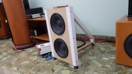
Added the third leg to the baffle so it is now free-standing. A little progress.
Unfortunately my Lynx Hilo soundacard has developed a failure which I've been troubleshooting with Lynx support, but seems I will need to send to them - that means a long waiting time since I'm in LatAm...painful. And imparts a delay on the project.
Anyway, looking into building an H frame to hang swinging baffleless 8" midrange and make makeasurements with a 2-way soundcard meanwhile.
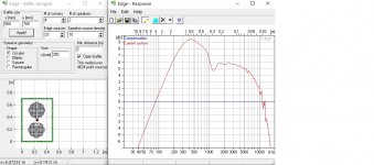
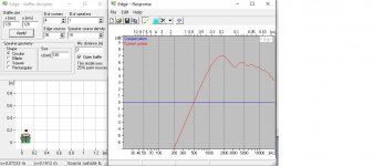
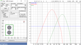
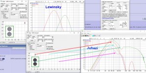
Attached the Edge simulations for 2x10" on the baffle and 8" baffleless. The latter is simulated as 145mm diameter since that is the cone diameter (without surround), and the square baffle has the same surface as a 145mm diameter circle.
From the sims it looks like the 2x10" on baffle should be ok up to 400Hz, and the 8" bafleless should be ok from 300-400Hz up to 1800Hz or so. Would you agree?
BTW, how do you graph two curves in Edge?
Unfortunately my Lynx Hilo soundacard has developed a failure which I've been troubleshooting with Lynx support, but seems I will need to send to them - that means a long waiting time since I'm in LatAm...painful. And imparts a delay on the project.
Anyway, looking into building an H frame to hang swinging baffleless 8" midrange and make makeasurements with a 2-way soundcard meanwhile.
Attached the Edge simulations for 2x10" on the baffle and 8" baffleless. The latter is simulated as 145mm diameter since that is the cone diameter (without surround), and the square baffle has the same surface as a 145mm diameter circle.
From the sims it looks like the 2x10" on baffle should be ok up to 400Hz, and the 8" bafleless should be ok from 300-400Hz up to 1800Hz or so. Would you agree?
BTW, how do you graph two curves in Edge?
Attachments
Last edited:
BTW, how do you graph two curves in Edge?
After first sim, press the blue cloud next to X, to freeze that plot
Then set parameters or move mic for second sim, and then you can freeze this plot and make third etc. Lines get different colors automatically.
After first sim, press the blue cloud next to X, to freeze that plot
Then set parameters or move mic for second sim, and then you can freeze this plot and make third etc. Lines get different colors automatically.
Midrange on swing
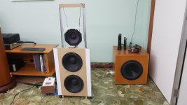
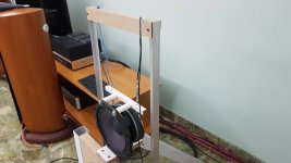
Inspired by threads I've seen, particularly mige0, I did a dirty test to keep the midrange baffleless and on a swing. The 8PE21 has about 3mm to the piece of wood attached to the 10" baffle. This is a test with materials I had at hand. Hanging on fishing line is on for a test, but I would think it will creep over time, so to be replaced with steel cable eventally.
The intent was to be able to measure the double 10" OB and 8" baffleless.
Attachments
Last edited:
I ran some mesurements...indoors...live in an apartment and can't easily do this outside. Does this render everything I measure useless?
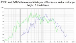
Attached the measurements of the 8PE21 baffleless, on a swing, measured on-axis and at 45 degrees horzontal. I applied 1/12 smoothing so we can readily see the 6 dB/octave slope. Nice to see it confirmed, BTW. It seems to me this could be ran from 300 to about 1500 or 1800Hz. Dipole peak is around 1500Hz. What do you think?
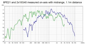
Also attached an overlay of 2x10G40 and 8PE21 on axis, and another at 45 degrees horizontal. Promising for the twin 10" to run from 60 to 300Hz (15 dB compensation required, dipole peak at 400Hz), and have the 8" from 300Hz to say 1500Hz (about 10dB compensation).
Eager to get your feedback! 🙂
PS: Thanks Juhazi for the tip on Edge!
Attached the measurements of the 8PE21 baffleless, on a swing, measured on-axis and at 45 degrees horzontal. I applied 1/12 smoothing so we can readily see the 6 dB/octave slope. Nice to see it confirmed, BTW. It seems to me this could be ran from 300 to about 1500 or 1800Hz. Dipole peak is around 1500Hz. What do you think?
Also attached an overlay of 2x10G40 and 8PE21 on axis, and another at 45 degrees horizontal. Promising for the twin 10" to run from 60 to 300Hz (15 dB compensation required, dipole peak at 400Hz), and have the 8" from 300Hz to say 1500Hz (about 10dB compensation).
Eager to get your feedback! 🙂
PS: Thanks Juhazi for the tip on Edge!
Attachments

I wouldn't lowpass above 800Hz, too much variations above 1kHz!
Why is mic so high in Edge sim? There is cancellation because of vertical source distance showing. This is real, but I wouldn't design anything based on that. Always take on-axis sim first to see "ideal" response. Off-axis sims are useful to find out where and when directivity gets messed up.
Attached is my sim with mic on mid-driver height and above it like in Lewinski's sim.
Attachments
- Home
- Loudspeakers
- Multi-Way
- 3-way open baffle plus subs