Actually I made a mistake it is a 32" 🙂 a friend gave it to me and I changed the 27" I had.
Anyway, we are looking around to find a decent price Projector but we are still waiting to find a High Definition one. Yes I also love projectors.
And yes it is weird to see my computer room with 5 computers, 4 LCD monitors and then go to the other room to find an almost 20 year old TV 🙁
Leo
Anyway, we are looking around to find a decent price Projector but we are still waiting to find a High Definition one. Yes I also love projectors.
And yes it is weird to see my computer room with 5 computers, 4 LCD monitors and then go to the other room to find an almost 20 year old TV 🙁
Leo
By the way since I am talking about my computers, I work doing 3D work so I also do 3D renders in case any of you need one for a speaker project or something else, just let me know, since you are helping me here the least I can do is do the same.
Leo
Leo
Hi,
The combined phaseshift of drivers and crossovers at the acoustic crossover comes to around 140 degrees based on initial sims in winisd. This tells me that most likely we need to invert the woofer.
As you already have nice models for the peavey woofer and test data for the Audax, could you export both as text files, frequency vs. SPL and frequency vs. Impdance? I can then run a few quick sims and finalise that area.
Ciao T
Here is what LEAP gives me for each driver. The light blue trace is the phase.
First, the Audax
An externally hosted image should be here but it was not working when we last tested it.
This is the Peavey
An externally hosted image should be here but it was not working when we last tested it.
Phase vs SPL
Audax, first:
Peavey:
Audax, first:
An externally hosted image should be here but it was not working when we last tested it.
Peavey:
An externally hosted image should be here but it was not working when we last tested it.
I'm not testing this combination, just watching. Anyway I follow wrong phase combinations from previous posts/threads, from your software I guess. But if you think a little, you can see that the xover on the woofer is like a second order electric (2 components), so you have to look at the combination with mid and measure (software) the shift between both. (Nothing that you don't know. Note: I hope your woofer (JBL) is correct now, and you're happy with your setup)🙂I don't understand why you are connecting the woofer out of phase for a first order filter, which has minimal phase shift.
Please explain.
Last edited:
I'm not testing this combination, just watching. Anyway I follow wrong phase combinations from previous posts/threads, from your software I guess. But if you think a little you can see that the xover on the woofer is like a second order electric (2 components), so you have to look at the combination with mid and measure (software) the shift between both. (Nothing that you don't know.)🙂
I am having a brain 'Break Wind Event' with this.
If we are using a 1st order passive crossover, we should have no phase reversal. I think I got that.
However, are you saying that the driver and enclosure are acting as a second order crossover and causing a phase mismatch?
I am struggling with LEAP, but how do I show that at the intended crossover point of 400 Hz?
Thanks!
Hi Loren,
Thank you for running these.
I do not use Leap myself. Can you see if you can EXPORT the response curves as TEXT files (e.g. tab delimited, one colume frequency, the other SPL and the same for imedance)?
Also, for the Audax Driver, could you export the response of your actual measurements? The Audax does not model well based on TS Parameters.
Graphs are not at all easy to import into my own modeling setup and I don't really have that much time to spend to this for this one-off.
Ciao T
Hi Loren,
That applies ONLY to the phase from the crossover.
Remember, our drivers (or rather driver/enclosure combo's) are MINIMUM phase, but NOT linear phase. So you need to add the excess phaseshift from the drivers to get the acoustical phase. And when you add the SPL from two drivers it is the acoustic phase that matters.
A good illustration of what happens if this simple is overlooked is the EPOS ES-25 (I am actually staggered how someone like Robin Marshall could get this wrong - I guess it happens to the best on occasion):
Stereophile: Epos ES25 loudspeaker
Basically, woofer and midrange connected in phase and out of nominal phase yields this:
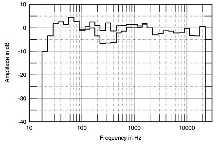
The graph with the suckout in the crossover region around 400Hz is the one with "in phase" connection, the flatter response is the one with the woofer reversed.
And trust me, this is quite audible!
Ciao T
If we are using a 1st order passive crossover, we should have no phase reversal.
That applies ONLY to the phase from the crossover.
Remember, our drivers (or rather driver/enclosure combo's) are MINIMUM phase, but NOT linear phase. So you need to add the excess phaseshift from the drivers to get the acoustical phase. And when you add the SPL from two drivers it is the acoustic phase that matters.
A good illustration of what happens if this simple is overlooked is the EPOS ES-25 (I am actually staggered how someone like Robin Marshall could get this wrong - I guess it happens to the best on occasion):
Stereophile: Epos ES25 loudspeaker
Basically, woofer and midrange connected in phase and out of nominal phase yields this:
The graph with the suckout in the crossover region around 400Hz is the one with "in phase" connection, the flatter response is the one with the woofer reversed.
And trust me, this is quite audible!
Ciao T
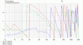
There's something wrong with the phase of the Audax (1). (?)Phase vs SPL
Audax, first:
An externally hosted image should be here but it was not working when we last tested it.
Peavey:
An externally hosted image should be here but it was not working when we last tested it.
-- Audax with xover -- necessary for the right total phase (shift) with Peavey (2). This one already has xover (?) and looks good. 50Hz (+180º) to 3000Hz (-180º)
Last edited:
There's something wrong with the phase of the Audax (1). (?)
-- Audax with xover -- necessary for the right total phase (shift) with Peavey (2). This one already has xover (?) and looks good.
Just the raw drivers, no crossover.
Then you need proper phases with xover applied and then check for right inversion (or not).Just the raw drivers, no crossover.
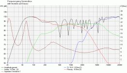
Here a simulation with different drivers with phase inversion already on woofer and minimal phase shift on software Boxsim (red-woofer/green lines-mid). (You should have something like this.)
ThorstenL, do you think that inductor (3.9mH) is going to be enough to protect the rest (high-mids) of the spectrum from it's interference with it's output and phases.
Attachments
Last edited:
Hi Loren,
Thank you for running these.
I do not use Leap myself. Can you see if you can EXPORT the response curves as TEXT files (e.g. tab delimited, one colume frequency, the other SPL and the same for imedance)?
Also, for the Audax Driver, could you export the response of your actual measurements? The Audax does not model well based on TS Parameters.
Graphs are not at all easy to import into my own modeling setup and I don't really have that much time to spend to this for this one-off.
Ciao T
Here are the files. The AudaxAD01.txt file (last one) is from measurements performed on my Audax in a .25 CuFt sealed enclosure, nearfield, using Fuzzmeasure.
The .txt files are the drivers from LEAP.
Audax LEAP
Peavey LEAP
Audax Fuzzmeasure
I only use Frd/Zma's but, again, as I said the phase from the Audax driver is inaccurate/defective. Sometimes it needs a few attempts (with the measuring equipment) to be smooth 🙂Here are the files. The AudaxAD01.txt file (last one) is from measurements performed on my Audax in a .25 CuFt sealed enclosure, nearfield, using Fuzzmeasure.
The .txt files are the drivers from LEAP.
Audax LEAP
Peavey LEAP
Audax Fuzzmeasure
Note: I didn't use data from the drivers Peavey-Audax, only their curves from files with data/specs from Visatons. (So the parameters are different from what it should be. Just for illustration.)
Attachments
Last edited:
I only use Frd/Zma's but, again, as I said the phase from the Audax driver is inaccurate/defective. Sometimes it needs a few attempts (with the measuring equipment) to be smooth 🙂
Note: I didn't use data from the drivers Peavey-Audax, only their curves from files with data/specs from Visatons. (So the parameters are different from what it should be. Just for illustration.)
The files are the same as .frd. Just change the extension to .frd and you are golden.
Hi Loren,
ThanX for these. Could you also export the impedance response?
I'll generate a FT17H model myself and then we are go to do some modeling.
Just by chance, you did not take an off-axis measurement of the Audax?
Ciao T
Here are the files.
ThanX for these. Could you also export the impedance response?
I'll generate a FT17H model myself and then we are go to do some modeling.
Just by chance, you did not take an off-axis measurement of the Audax?
Ciao T
As I said both files for the Audax don't work. Unless you use output/dB's only and no phases. I don't know how you work with Audax frd incomplete.😕 The curve output (I used for the Audax) is from file audaxleap01, phase is useless. I don't know what measurements are in the other file audaxAD01, it doesn't make any sense to me. Curves for the Peavey (output/phase that I used from file Peavey01) are ok as I already said.🙂 I don't feel like I have gold when someone gives me a lemon.🙄The files are the same as .frd. Just change the extension to .frd and you are golden.
On another note, I have to say that, ThorstenL approach looks like very close to a very good workable solution (as we can see on simulation from #173 with different data but same xover).

Last edited:
As I said both files for the Audax don't work. Unless you use output/dB's only and no phases. I don't know how you work with Audax frd incomplete.😕 The curve output (I used for the Audax) is from file audaxleap01, phase is useless. I don't know what measurements are in the other file audaxAD01, it doesn't make any sense to me. Curves for the Peavey (output/phase that I used from file Peavey01) are ok as I already said.🙂 I don't feel like I have gold when someone gives me a lemon.🙄
Still learning here (new software), but I'll take another stab at it and repost that data.
I'll also dig up what I have for the Audax off-axis plots.
As I said both files for the Audax don't work. Unless you use output/dB's only and no phases. I don't know how you work with Audax frd incomplete.😕 The curve output (I used for the Audax) is from file audaxleap01, phase is useless. I don't know what measurements are in the other file audaxAD01, it doesn't make any sense to me. Curves for the Peavey (output/phase that I used from file Peavey01) are ok as I already said.🙂 I don't feel like I have gold when someone gives me a lemon.🙄
On another note, I have to say that, ThorstenL approach looks like very close to a very good workable solution (as we can see on simulation from #173 with different data but same xover).
I do not have response data for the Audax that incorporates phase data, nor do I have off-axis.
However, I will make an effort to re-run those plots using HolmImpulse.
There may be two issues I can see.
1. Due to the room, I may not be able to get a response low enough before room reflections impact the signal.
Gating can be done, but it will likely cut the low end off before the tail of the Audax's lower end response reaches its asymptote.
2. I have no experience with HolmImpulse, but it claims that it can accurately measure phase. So, I am willing to give it a run.
When I am able to do this may be another matter, but hopefully in a few days. I need this data any way to redo the crossover on my 3-way.
Lastly, I am still working on the LEAP version of the Audax response. The phase plot really just looks like a constant delay offset rather than true phase and I don't know why, but I will find out.
Loren42, I read your PM's. We can discuss some points of view, if you want, any time. In the mean time, on the Audax, when measuring I had that problem of the inconsistent phase (with other drivers), and needed some 5 or 6 measurements (solution from the engineer of the measurement software, I can't remember why😕) to get it right (to make it smooth). The lower part of the output you can glue to the portion you measure, I guess.🙂
Loren42, I read your PM's. We can discuss some points of view, if you want, any time. In the mean time, on the Audax, when measuring I had that problem of the inconsistent phase (with other drivers), and needed some 5 or 6 measurements (solution from the engineer of the measurement software, I can't remember why😕) to get it right (to make it smooth). The lower part of the output you can glue to the portion you measure, I guess.🙂
I have a number of issues right now.
1. My workload has increased. I am still at work as I write. That will probably take a few days before it slows down enough that I can haul out the equipment and start some more runs.
2. I may have some limits with regard to room as far as getting a low enough frequency response to determine the low frequency tail of the Audax. My room is pretty live and about 15' by 30'.
Outside is usually pretty windy, so opportunities for measuring outside are rare, but the swimming is good 9 months of the year. 🙂
- Status
- Not open for further replies.
- Home
- Loudspeakers
- Multi-Way
- 3 Way crossover details...