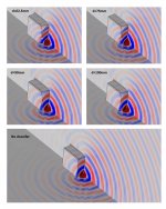
Counting the wavelengths on the baffle seems to show plots at different frequencies.
Yes, it's 1.5kHz for the first two plots and 5kHz for the rest. I'll correct this as soon as I can.
Here is the corrected figure. Sorry, I seem to have updated the frequency for the cross-sectional slices but forgot to do it for the enclosure surface plot. Now they are all for f=1589Hz. Perhaps now it's easier to see how the polars get tidier at this frequency range when the chamfer width is not too close to lambda/2. One could even say that the widest chamfer is worse than no chamfer at al.
Attachments
Last edited:
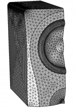
I used triangular elements with quadratic discretization for pressure and linear for normal acceleration. The mesh is generated in this order: tweeter dome -> coax cone -> baffle -> rest of the enclosure. Consequently, it starts with a circular pattern (driver) and morphs into a square pattern (enclosure). Perhaps using triangular elements for the driver and quad for the rest might be good option. I'm getting average mesh element quality of 0.9 with the current method. The maximum mesh element size is 16mm, but around the driver and most edges it's finer (~3-8mm).
This suggests numerical error should be good below about 5 kHz with no gross issues below 20 kHz (i.e. element order and number per wavelength). Linear wave equation seems fine for the application given no apparent sources of sound within the fluid only at the boundary. Leaving the only significant error sources to consider to be those stemming from the boundary conditions not being fully aligned with reality (e.g. woofer shape, missing phase plug/waveguide,...). Looking good.
I can do that at some point, but I have some homework to do on lumped model. In any case at best I can provide a comparison of the two approaches for a specific case. I don't think I am the right person to make any general conclusions about the computation methodology.
Providing reliable data is a significant step. Interpretation may or may not be significant depending on what is shown. What we want to see is differences clearly aligning with failing assumptions in the models. This not only builds confidence in the more complete model but can often help teach how to interpret/extrapolate the results from the simpler model towards the likely reality.
It has been repeated on this forum, and in this thread, that the edge rounding should ideally begin right at the edge of the driver, i.e. maximal rounding size or alternatively minimal baffle dimensions. On the other hand, it is often said that a chamfer works just as well as a roundover. I just wanted to point out that the chamfer is effectively a facet of the baffle and there is diffraction from the edges of the facet. Hence the chamfer size should be considered from the diffraction point of view instead of just making it as large as possible.
With BEM you have a tool with which to optimise a baffle/cabinet shape outside the waveguide formed by the midrange cone. Diffraction from sharp edges are not necessarily harmful when close to a sound source. The DXT waveguide for example uses a set of sharp edges to create a smaller device than would be required with smooth walls.
In the end I'm an experimentalist though🙂
Never mind.
This suggests numerical error should be good below about 5 kHz with no gross issues below 20 kHz (i.e. element order and number per wavelength). Linear wave equation seems fine for the application given no apparent sources of sound within the fluid only at the boundary. Leaving the only significant error sources to consider to be those stemming from the boundary conditions not being fully aligned with reality (e.g. woofer shape, missing phase plug/waveguide,...). Looking good.
Thank you. That's the wavelength range I was indeed aiming at when building the model. As you pointed out earlier, the important frequency range from the baffle design point of view is below 6kHz or so. I don't intend to model the phase plug because that would probably require a very refined model and take some iterations comparing simulations and measurements to get right. This is one uncertainty that I just have to live with. Measurements will tell... Next round is in the pipeline and it includes the woofer.
With BEM you have a tool with which to optimise a baffle/cabinet shape outside the waveguide formed by the midrange cone. Diffraction from sharp edges are not necessarily harmful when close to a sound source. The DXT waveguide for example uses a set of sharp edges to create a smaller device than would be required with smooth walls.
Indeed. It's all about controlling the diffraction since it's always present anyway. DXT is a very good example and Heissman's DXT-MON is a great example of a successful execution.
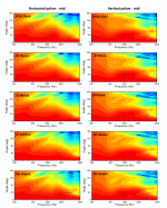
The first iteration with woofers is with the typical woofer mounting: recessed woofers mounted on the front side of the baffle. SB23mfcl45 has a fat surround because of the long stroke so some disturbance is expected. The horizontal polars are not much affected, but the verticals are uglier.
The vertical dashed lines in the plots indicate the intended XO points.
These show also the first results for the woofer response. I think there's nothing very interesting in that respect. The vertical polars show the expected lobing, but it's not an issue with XO at 200-300Hz. Just some additional vertical directivity provided by the twin woofers.
My plan is to mount the woofers on the backside of the baffle, so next I will try how the response is affected if the highest point of the woofer surround is in the plane of the baffle. I'll also planarize the gap between the baffle and the highest point of the surround (this can be done with a 3D printed ring). Hart to explain, but you'll get it from the figures when I post them.
Attachments
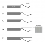
I have been thinking about the role of woofers on the polar response. The simulation above is for option A. I'm currently working on a simulation for option C (simply because it's easier to mesh than option B), but I doubt that it will fix the vertical response since some the problems are at quite long wavelengths (<1kHz).
Option D: Any thoughts on the effect of a metal grill?
Option E: Are they any other good examples E besides Genelec 83x1 series? I suppose the woofers could be behind a the baffle and fire through some slots in the front.

Option D: Any thoughts on the effect of a metal grill?
Option E: Are they any other good examples E besides Genelec 83x1 series? I suppose the woofers could be behind a the baffle and fire through some slots in the front.
Attachments

Last edited:
Would C & D even allow enough movement of the surround to account for excursion?
Obviously not so much an issue for mids, but for woofers...?
Obviously not so much an issue for mids, but for woofers...?
Would C & D even allow enough movement of the surround to account for excursion?
Obviously not so much an issue for mids, but for woofers...?
In the sketch it looks problematic, but it can be designed not to interfere.
Not as sketch I believe... surround will move upwards and it will hit the solid structures your draw.
//
//
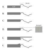
I would suggest adding to the list a simulation of the bump K&H/Neumann use around their woofers. I don't know the reasoning which may not be wholly apparent from solutions of the linear wave equation but since they design and manufacture speakers with a high technical performance it might be useful to know.
I would suggest adding to the list a simulation of the bump K&H/Neumann use around their woofers. I don't know the reasoning which may not be wholly apparent from solutions of the linear wave equation but since they design and manufacture speakers with a high technical performance it might be useful to know.
Thank you. Neumann style added as option F, but being practical and easy to model, it's much closer to the top of the list of things to test.
Attachments
Take a close look at Accuton drivers.In the sketch it looks problematic, but it can be designed not to interfere.
Take a close look at Accuton drivers.
Good point. They seem to use a grill with a very small fill factor.

Hello,
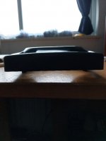
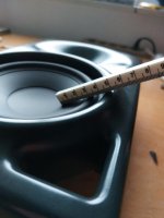
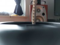
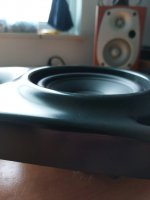
Have a Neumann KH120 baffle laying around, so maybe you like these photo's.
The woofer is mounted deeper than in your pictures, i measure 13mm.
When i place a ruler on top of the cone and baffle-protrusion it touches the roll surround exactly. This is key when mounting the driver from behind the baffle
I copied this mounting method on a test baffle and found that it had a positive effect on the off-axis frequency curves, ie a lot smoother than the same driver flush mounted. Sadly i don't have these measurements anymore.
Greetings, Jeroen
Attachments
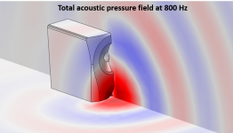
I have ran some simulations for some variations of A, B, C, and F, but 800Hz is so long wavelength that tinkering small stuff around to woofer surround doesn't really affect anything. Remaining options are to
- Find a woofer which has flatter cone. This is unlikely unless I rethink the whole concept or start playing with car audio drivers.
- Bring the woofer forward by several cm and add a Neumann style lip around it. According to simulations, this helps a bit because the 800Hz waves see that woofer as shallower obstruction if it's pushed forward, but not worth the effort IMO. It also has a small negative effect on the horizontal response.
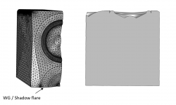
- Accept some irregularities in the vertical response and move forward. This is what I am most likely going to do. I have already done some simulations using small waveguide or shadow flare around the coaxial driver in this woofer-coax-woofer configuration, but more on that later.
Attachments
Are you guys familiar with this 2D sim FineCone by Loudsoft Peter Larsen? It models eg. phase plug effects
https://www.loudsoft.com/fine-design-software/
https://www.loudsoft.com/finecone/
https://www.loudsoft.com/fine-design-software/
https://www.loudsoft.com/finecone/
Last edited:
^I am not familiar with those.
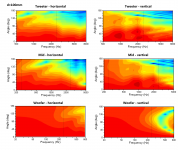
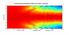
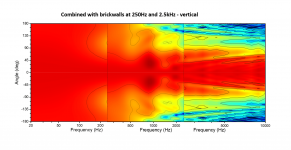
Here are the results from COMSOL for the woofer-coax-woofer with a flare (or waveguide). The polars are shown here for each driver in the familiar VituixCAD style with 6db contours. The intended XO frequencies are indicated by the vertical dashed lines. The last two attachments are cut-and-glue sketches showing how these would combine as the full spectrum of the speaker. The horizontal response is very nice with fairly constant directivity down to 500Hz. As discussed above, the vertical polars suffer from the diffraction from the woofers. At the moment I don't have ideas how to improve that, but I'll simulate these again with more accurate woofer shape once I receive the SB23 drivers (which I have ordered).
Here are the results from COMSOL for the woofer-coax-woofer with a flare (or waveguide). The polars are shown here for each driver in the familiar VituixCAD style with 6db contours. The intended XO frequencies are indicated by the vertical dashed lines. The last two attachments are cut-and-glue sketches showing how these would combine as the full spectrum of the speaker. The horizontal response is very nice with fairly constant directivity down to 500Hz. As discussed above, the vertical polars suffer from the diffraction from the woofers. At the moment I don't have ideas how to improve that, but I'll simulate these again with more accurate woofer shape once I receive the SB23 drivers (which I have ordered).
Attachments


and here's Genelec 8361A measurement data to compare with.
https://www.audiosciencereview.com/...s/genelec-8361a-review-powered-monitor.28039/


https://www.audiosciencereview.com/...s/genelec-8361a-review-powered-monitor.28039/
- Home
- Loudspeakers
- Multi-Way
- 3-way active standmounts with coax upper end & Other UniQ adventures