Not too far off by looks. Are you intending to play a bit more with the midrange response?
I know you are perhaps not the right person to ask but do you know what 0 dB means in the Genelec plots? I like the style of 20 odd constant colour bands compared to a gradient (looks nice but difficult to read values off) or a gradient with lines (bit cluttered with enough to read values off).
I know you are perhaps not the right person to ask but do you know what 0 dB means in the Genelec plots? I like the style of 20 odd constant colour bands compared to a gradient (looks nice but difficult to read values off) or a gradient with lines (bit cluttered with enough to read values off).
There isn't many degrees of freedom left in this design, but sure, I will run more tests. Anyway first I have to wait for the woofers to arrive so that I can measure their shape. Now I'm using a rough estimate based on the drawings and photos available online. I think a larger chamfer around to woofer might since it kind of pulls the baffle back closer to the level of the woofer cone as far as it's seen by those ~1kHz waves.Not too far off by looks. Are you intending to play a bit more with the midrange response?
I know you are perhaps not the right person to ask but do you know what 0 dB means in the Genelec plots? I like the style of 20 odd constant colour bands compared to a gradient (looks nice but difficult to read values off) or a gradient with lines (bit cluttered with enough to read values off).
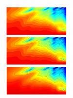
Hmm. Perhaps black contour lines every 6 dB and constant color contours every 1 or 2 dB would be optimal for showing both the forest and the trees at the same time. (edit. figure added.)
Sorry I can't help you much regarding the Klippel data. I think ASR usually shows the polars without normalization, but those look like they are normalized to the on-axis. Another plot on the same page states that it's 86 dSPL on tweeter axis. Here's similar data for the smaller 8351 without normalization.
Attachments
Last edited:
A straight chamfer added in front of the driver can have quite a positive influence on directivity in the right circumstances too.Thank you. Neumann style added as option F, but being practical and easy to model, it's much closer to the top of the list of things to test.
https://www.diyaudio.com/community/...ver-full-range-line-array.242171/post-6524791
Thank you. That's definitely something to consider. The problem is though that such chamfer would push back the woofer even deeper with respect to the baffle level which in this design might amplify the problems at around 800Hz. At least making the woofer cone deeper has that effect.A straight chamfer added in front of the driver can have quite a positive influence on directivity in the right circumstances too.
https://www.diyaudio.com/community/...ver-full-range-line-array.242171/post-6524791
As you pointed out in the other thread, simulating the woofer as a hard reflective boundary (as I have done) probably exaggerates these issues. I have to see what options I have to make the woofer cone lossy in COMSOL without building a full electro-acousto-mechanic model of the driver and enclosure. So if we assume that the pressure waves hitting the woofer cone will couple to the sealed internal volume of the enclosure, perhaps the problematic frequencies could be cleverly absorbed there, for example, using properly tuned metamaterial.
Actually what I wrote above is not true since it looks like your chamfer ends to the level of the driver mounting flange. I can add such chamfer to my latest model without moving the woofer at all. Definitely worth testing!A straight chamfer added in front of the driver can have quite a positive influence on directivity in the right circumstances too.
https://www.diyaudio.com/community/...ver-full-range-line-array.242171/post-6524791
Don't we all. There's always some lesson to be learned.I love Fluid's sims 🙂
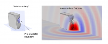
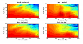
So in attempt to understand how much I may overestimate the the influence of the woofer shape on the midrange response, defined the woofer cone as a soft boundary. This means that the pressure at the woofer boundary is set to zero. The horizotal polars are largely unaffected by this change, but the problems at 800Hz disappear completely. On one hand this confirms that it was related to the woofer as expected. On the other hand, it suggests that losses in the woofer area for will improve the midrange response of this speaker. The truth is probably somewhere in the middle, and it's not clear to my how much losses I can expect to see in real life measurements.
Attachments
Thanks, always good to know they have utility to someone else as well.I love Fluid's sims 🙂
This is a good test, I would apply the same condition to the surround to see what effect it is adding when considered as a rigid boundary. Have you run a baseline sim of the overall cabinet but with the woofers out and just a plain baffle in their place? I find this useful to see the box contribution as a separate entity.So in attempt to understand how much I may overestimate the the influence of the woofer shape on the midrange response, defined the woofer cone as a soft boundary.
Agreed without some decent materials knowledge or empirical testing it is hard to know. I would optimize for the soft boundary and let real life be what it is at least until the prototype stage when you will have some real life data to base decisions on.The truth is probably somewhere in the middle, and it's not clear to my how much losses I can expect to see in real life measurements.
As a general comment I imagine when you use a crossover to blend the directivities the end result should actually be pretty good with what you have now.
Thank you. I'm just setting up a simulation with both cone and surround set as soft boundaries. This same box with the coaxial driver without woofers was my starting point for the COMSOL work. It's all scattered in this thread, but I'll wrap up with some conclusions on the woofer issues once I have run one more test, which is for a larger dust cap for making the woofer shallower.This is a good test, I would apply the same condition to the surround to see what effect it is adding when considered as a rigid boundary. Have you run a baseline sim of the overall cabinet but with the woofers out and just a plain baffle in their place? I find this useful to see the box contribution as a separate entity.
Agreed without some decent materials knowledge or empirical testing it is hard to know. I would optimize for the soft boundary and let real life be what it is at least until the prototype stage when you will have some real life data to base decisions on.
Agreed without some decent materials knowledge or empirical testing it is hard to know. I would optimize for the soft boundary and let real life be what it is at least until the prototype stage when you will have some real life data to base decisions on.
Yeah, I should start moving towards building the prototype. It's a good timing for that since I should also get more practice with CNC. The intended XO frequencies are indicated by the dashed lines in the plots. I think the horizontal part is already very good and should be easy the blend as a nice overall directivity. The vertical part is more problematic, but measurements will show the true nature of those woofer issues.As a general comment I imagine when you use a crossover to blend the directivities the end result should actually be pretty good with what you have now.
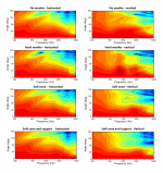
Here I have included the response without woofers, with reflective woofers, and two cases of soft woofers (P=0). First being soft cone and reflective surround, and the second with soft boundary for both cone and surround.
The relevant baffle dimensions in terms of the vertical response:
From the center of the coaxial driver to the baffle edge in the vertical direction = 350 mm
Vertical center-to-center distance between the coaxial driver and the woofers = 212 mm
I tried to have these dimensions as close to the golden ratio as possible so that they don't amplify each other. But still, it seems that a lossy woofer can reduce the baffle diffraction effects of the enclosure. It's not a surprise since we are effectively applying losses for the waves propagating up or down towards the baffle edges. It's going to be interesting to see the measurements because they can be anything between worse than without the woofers and better than without the woofers.
Attachments
This message summarizes the simulations that I have performed for different ways of mounting the woofers. The source in all of these is the coaxial cone of the Q100 driver (which is the mid of this speaker).
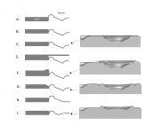
Below is the list of the simulated geometries, which are also illustrated in the sketch. For some of them I have included also cropped pictures of the actual simulation geometry from COMSOL. All of these are modeled assuming the woofer incl. the surround as hard reflective boundaries for the pressure waves. As discussed above, that is not necessarily the reality, but it still serves the purpose of demonstrating the effect of the geometry. D is missing from the sketch because I have not simulated it.
A. Normal flush-mounted woofer
B. Recessed woofer
C. Recessed woofer without gap between baffle and surround
D. (Recessed woofer with metal grill. Not tested)
E. No woofers or woofers hidden behind the baffle <-- Refenrece
F. Recessed woofer with “Neumann-style” ring
G. Recessed woofer with chamfer
H. Like A but with flat dust cap
I. Like A but with larger diameter dustcap
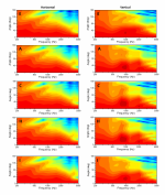
The second picture shows the polar responses for some of the simulated geometries. I have chosen those that actually show some differences. E represents the reference case without woofers (or woofers hidden behind the baffle as in Genelec 8341). This has the cleanest vertical response. The other geometries have some woofer-related issues in the vertical response just below 1000 Hz. The horizontal response is pretty much the same in all cases. Adjusting small stuff around the woofer (e.g. hiding the surround, chamfers etc.) has no influence on the investigated features in the investigated enclosure. The only thing that seems to matter here is how big hole the woofer makes for those ~1000Hz waves to diffract from. Therefore, recessing the woofer (C) has a slight negative effect in comparison with typical flush-mounting (A). The biggest improvement is achieved by using a shallower woofer (I). I chose to do this by installing a wider dust cap because that is something that in could at least in principle actually do.
Note also that F can provide some improvement if the woofer is brought significantly forward and the “Neuman style” ring is used for softening the step between the baffle and the woofer flange. I have seen some mild improvement in some simulations that don’t fit in this data set for other reasons. Such structure placed close to the coaxial driver may have a negative effect on the higher frequencies though.
Below is the list of the simulated geometries, which are also illustrated in the sketch. For some of them I have included also cropped pictures of the actual simulation geometry from COMSOL. All of these are modeled assuming the woofer incl. the surround as hard reflective boundaries for the pressure waves. As discussed above, that is not necessarily the reality, but it still serves the purpose of demonstrating the effect of the geometry. D is missing from the sketch because I have not simulated it.
A. Normal flush-mounted woofer
B. Recessed woofer
C. Recessed woofer without gap between baffle and surround
D. (Recessed woofer with metal grill. Not tested)
E. No woofers or woofers hidden behind the baffle <-- Refenrece
F. Recessed woofer with “Neumann-style” ring
G. Recessed woofer with chamfer
H. Like A but with flat dust cap
I. Like A but with larger diameter dustcap
The second picture shows the polar responses for some of the simulated geometries. I have chosen those that actually show some differences. E represents the reference case without woofers (or woofers hidden behind the baffle as in Genelec 8341). This has the cleanest vertical response. The other geometries have some woofer-related issues in the vertical response just below 1000 Hz. The horizontal response is pretty much the same in all cases. Adjusting small stuff around the woofer (e.g. hiding the surround, chamfers etc.) has no influence on the investigated features in the investigated enclosure. The only thing that seems to matter here is how big hole the woofer makes for those ~1000Hz waves to diffract from. Therefore, recessing the woofer (C) has a slight negative effect in comparison with typical flush-mounting (A). The biggest improvement is achieved by using a shallower woofer (I). I chose to do this by installing a wider dust cap because that is something that in could at least in principle actually do.
Note also that F can provide some improvement if the woofer is brought significantly forward and the “Neuman style” ring is used for softening the step between the baffle and the woofer flange. I have seen some mild improvement in some simulations that don’t fit in this data set for other reasons. Such structure placed close to the coaxial driver may have a negative effect on the higher frequencies though.
Attachments

Looking forward to seeing the measurements as it should give a clearer picture on how much of the hard boundary issues remain.It's going to be interesting to see the measurements because they can be anything between worse than without the woofers and better than without the woofers.
I made a synergy simulation that made the result look awful due to all the hard boundaries but in reality it is nowhere near as bad. There is a damping that takes place in the port and without including it the result is not accurate, but just as here trying to guess the amount of damping is tricky.
Have you read this paper by Joerg Panzer
http://www.randteam.de/Publications/Pub_Aes112_Radiation_Impedance_Cones.html
I suspect COMSOL behaves much like ABEC in basic BEM mode. This has an effect on the relative depth created by recessing the drivers and can make the higher frequencies inaccurate in deeper cones. 1K is still within the accurate range but interesting nonetheless I think.
Thank you for the link fluid. I wasn't aware of this work. I have to read it again when I'm less tired, but it's clearly relevant.Looking forward to seeing the measurements as it should give a clearer picture on how much of the hard boundary issues remain.
I made a synergy simulation that made the result look awful due to all the hard boundaries but in reality it is nowhere near as bad. There is a damping that takes place in the port and without including it the result is not accurate, but just as here trying to guess the amount of damping is tricky.
Have you read this paper by Joerg Panzer
http://www.randteam.de/Publications/Pub_Aes112_Radiation_Impedance_Cones.html
I suspect COMSOL behaves much like ABEC in basic BEM mode. This has an effect on the relative depth created by recessing the drivers and can make the higher frequencies inaccurate in deeper cones. 1K is still within the accurate range but interesting nonetheless I think.
BTW, I will use SB23MFCL45 woofers which are on the stiff side was far as the suspension goes, but the poly cone has breakup close to 1kHz so there's definitely all sorts of mechanical modes available in that range.
Today was an exciting day at the workshop! Machining the front panels was by far the most challenging task in my short CAM career, but the result is quite satisfying. Just some small issues that have to be fixed manually. The v-groove bit that I used for the chamfer traces was not a perfect v, so the tip left grooves that have to be filled or sanded out. I also have to enlarge the woofer recess diameter a little bit since spec + 0.6mm tolerance was not enough to fit the SB23s.

Thank you Martin. I should be able to machine the rest of the MDF parts next week so slowly moving towards actually building the enclosures.
Machinig looks good, nice sharp edges. Did you used 2x18mm MDF sandwich?
I'm starting to look for a CNC router ... May I ask what machine you use for machining?
I'm starting to look for a CNC router ... May I ask what machine you use for machining?
It's two layers of 22 mm MDF stacked for the front panel. I had planned 19 mm MDF for everything else, but availability dictates so it's going to be 21 mm.
The router is Excitech E2-1325. I don't know how it compares to other 3-axis CNC routers because this is my first love. There's also a small 5-axis machine (POCKET NC V2-10) in the same room but haven't learned how to use it yet.
The router is Excitech E2-1325. I don't know how it compares to other 3-axis CNC routers because this is my first love. There's also a small 5-axis machine (POCKET NC V2-10) in the same room but haven't learned how to use it yet.
Hooo, it looks like professional machine.👍 I'm looking for something for home use, I can imagine your machine costs approximately 60000€ without accessories?
What do you think about this assembly?
https://www.avidcnc.com/index.php
What do you think about this assembly?
https://www.avidcnc.com/index.php
- Home
- Loudspeakers
- Multi-Way
- 3-way active standmounts with coax upper end & Other UniQ adventures